Alternating Current Overview
Get insights from 72 questions on Alternating Current Overview, answered by students, alumni, and experts. You may also ask and answer any question you like about Alternating Current Overview
- 72
Questions
- 0
Discussions
- 0
Active Users
- 0
Followers
Have a question about Alternating Current Overview? Ask our experts
Keep it short & simple. Type complete word. Avoid abusive language.

In a circuit consisting of a capacitance and a generator with alternating emf Eg = <!-- [if gte mso 9]><xml>
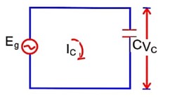
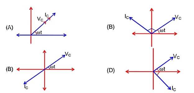
In a circuit consisting of a capacitance and a generator with alternating emf Eg = <!-- [if gte mso 9]><xml>
For capacitor : current leads emf
by 90°.
 Upvote

A series LCR circuit of R = <!-- [if gte mso 9]><xml>
A series LCR circuit of R = <!-- [if gte mso 9]><xml>
Power dissipated in cycle = P =
For resonance, z = R, so
Upvote For a series LCR circuit with R = 100 <!-- [if gte mso 9]><xml>
For a series LCR circuit with R = 100 <!-- [if gte mso 9]><xml>
Since XC is approximately infinite, so the phase angle between current and supplied voltage and the nature of the circuit is
Upvote At very high frequencies, the effective impendance of the given circuit will be_______ <!-- [if gte mso 9]><xml>
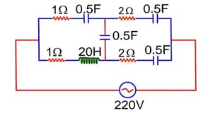
At very high frequencies, the effective impendance of the given circuit will be_______ <!-- [if gte mso 9]><xml>
Upvote The alternating current is given by
The r.m.s. value of this current is……….A.
The alternating current is given by
The r.m.s. value of this current is……….A.
A circuit is arranged as shown in figure. The output voltage V0 is equal to………V.
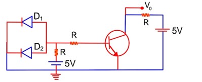
A circuit is arranged as shown in figure. The output voltage V0 is equal to………V.
Since resistance is zero in forward bias.
=> V0 = 5V
Upvote In the given circuit the AC source has <!-- [if gte mso 9]><xml>
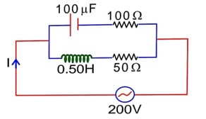
In the given circuit the AC source has <!-- [if gte mso 9]><xml>
Let, current through inductor,
Let, current through capacitor,
As
Views|Posted a year ago
Purely inductive circuit
Average power = 0
Upvote