
Alternating Current Overview
Get insights from 72 questions on Alternating Current Overview, answered by students, alumni, and experts. You may also ask and answer any question you like about Alternating Current Overview
- 72
Questions
- 0
Discussions
- 0
Active Users
- 0
Followers
Have a question about Alternating Current Overview? Ask our experts
Keep it short & simple. Type complete word. Avoid abusive language.
As shown in the figure an inductor of inductance 200 mH is connected to an AC source of emf 220 V and frequency 50 Hz. The instantaneous voltage of the source is 0 V when the peak value of current is <!-- [if gte mso 9]><xml>
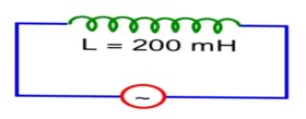
As shown in the figure an inductor of inductance 200 mH is connected to an AC source of emf 220 V and frequency 50 Hz. The instantaneous voltage of the source is 0 V when the peak value of current is <!-- [if gte mso 9]><xml>
Let l = l0 cos wt
Then v = v0 sinwt
at t = 0, v = 0
but l = l0
a = 121 × 2
a = 242
 Upvote

A resistance of 40Ω <!-- [if gte mso 9]><xml>
A resistance of 40Ω <!-- [if gte mso 9]><xml>
Let l = l0 cos wt
l = l0, at t1 = 0
&
= 0.25 × 10⁻²
t2 = 2.5 ms
Upvote For a series LCR circuit, I vs <!-- [if gte mso 9]><xml>
Choose the most appropriate answer from the options given below:

For a series LCR circuit, I vs <!-- [if gte mso 9]><xml>
Choose the most appropriate answer from the options given below:
At wr impedance of the circuit is equal to the resistance of the circuit.
Left of wr, circuit is mainly capacitive
Right of wr, the circuit is mainly Inductive.
Upvote 7.26 Do the same exercise as above with the replacement of the earlier transformer by a 40,000-220 V step-down transformer (Neglect, as before, leakage losses though this may not be a good assumption any longer because of the very high voltage transmission involved). Hence, explain why high voltage transmission is preferred?
7.26 Do the same exercise as above with the replacement of the earlier transformer by a 40,000-220 V step-down transformer (Neglect, as before, leakage losses though this may not be a good assumption any longer because of the very high voltage transmission involved). Hence, explain why high voltage transmission is preferred?
7.26 The rating of step-down transformer = 40000 V – 220 V
Hence, the input voltage, = 40000 V
Output voltage, = 220 V
Total electric power required, P = 800 kW = 800 W
Source potential, V = 220 V
Voltage at which electric plant generates power, V’ = 440 V
Distance betwe
Upvote 7.25 A small town with a demand of 800 kW of electric power at 220 V is situated 15 km away from an electric plant generating power at 440 V. The resistance of the two wire line carrying power is 0.5 Ω per km. The town gets power from the line through a 4000-220 V step-down transformer at a sub-station in the town.
(a) Estimate the line power loss in the form of heat.
(b) How much power must the plant supply, assuming there is negligible power loss due to leakage?
(c) Characterize the step up transformer at the plant.
7.25 A small town with a demand of 800 kW of electric power at 220 V is situated 15 km away from an electric plant generating power at 440 V. The resistance of the two wire line carrying power is 0.5 Ω per km. The town gets power from the line through a 4000-220 V step-down transformer at a sub-station in the town.
(a) Estimate the line power loss in the form of heat.
(b) How much power must the plant supply, assuming there is negligible power loss due to leakage?
(c) Characterize the step up transformer at the plant.
7.25 Total electric power required, P = 800 kW = 800 W
Supply voltage, V = 220 V
Electric plant generating voltage, V’ = 440 V
Distance between the town and power generating station, d = 15 km
Resistance of the two wires lines carrying power = 0.5 Ω /km
Total resistance of the wire, R = 2
Upvote 7.24 At a hydroelectric power plant, the water pressure head is at a height of 300 m and the water flow available is 100 m3s–1. If the turbine generator efficiency is 60%, estimate the electric power available from the plant (g = 9.8 ms–2 ).
7.24 At a hydroelectric power plant, the water pressure head is at a height of 300 m and the water flow available is 100 m3s–1. If the turbine generator efficiency is 60%, estimate the electric power available from the plant (g = 9.8 ms–2 ).
7.24 Height of the water pressure head, h = 300 m
Volume of water flow rate, V = 100 /s
Efficiency of turbine generator, = 60 % = 0.6
Acceleration due to gravity, g = 9.8 m/
Density of water, = kg/
Therefore, electric power available from the plan
Upvote 7.23 A power transmission line feeds input power at 2300 V to a step-down transformer with its primary windings having 4000 turns. What should be the number of turns in the secondary in order to get output power at 230 V?
7.23 A power transmission line feeds input power at 2300 V to a step-down transformer with its primary windings having 4000 turns. What should be the number of turns in the secondary in order to get output power at 230 V?
7.23 Input voltage, = 2300 V
Number of turns in primary coil, = 4000
Output voltage, = 230 V
Number of turns in secondary coil =
From the relation of voltage and number of turns, we get
= or = = 400
Hence, there are 400 turns
Upvote 7.21 Obtain the resonant frequency and Q-factor of a series LCR circuit with L = 3.0 H, C = 27 μF, and R = 7.4 Ω. It is desired to improve the sharpness of the resonance of the circuit by reducing its ‘full width at half maximum’ by a factor of 2. Suggest a suitable way.
7.21 Obtain the resonant frequency and Q-factor of a series LCR circuit with L = 3.0 H, C = 27 μF, and R = 7.4 Ω. It is desired to improve the sharpness of the resonance of the circuit by reducing its ‘full width at half maximum’ by a factor of 2. Suggest a suitable way.
7.21 Given values of the LCR circuit
L = 3.0 H, C = 27 F, R = 7.4 Ω
At resonance, the angular frequency, = = = 111.11 rad/s
Q factor of the series, Q = = = 45.045
To improve the sharpness of the resonance by reducing its ‘full width at h
Upvote 7.20 A series LCR circuit with L = 0.12 H, C = 480 nF, R = 23 Ω is connected to a 230 V variable frequency supply.
(a) What is the source frequency for which current amplitude is maximum. Obtain this maximum value.
(b) What is the source frequency for which average power absorbed by the circuit is maximum. Obtain the value of this maximum power.
(c) For which frequencies of the source is the power transferred to the circuit half the power at resonant frequency? What is the current amplitude at these frequencies?
(d) What is the Q-factor of the given circuit?
7.20 A series LCR circuit with L = 0.12 H, C = 480 nF, R = 23 Ω is connected to a 230 V variable frequency supply.
(a) What is the source frequency for which current amplitude is maximum. Obtain this maximum value.
(b) What is the source frequency for which average power absorbed by the circuit is maximum. Obtain the value of this maximum power.
(c) For which frequencies of the source is the power transferred to the circuit half the power at resonant frequency? What is the current amplitude at these frequencies?
(d) What is the Q-factor of the given circuit?
7.20 Inductance, L = 0.12 H
Capacitance, C = 480 nF = 480 F
Resistance, R = 23 Ω
Supply voltage, V = 230 V
Peak voltage is given as, = = 325.27 V
Current flowing in the circuit is given by the relation,
where = maximum at resonance
, where
Upvote 7.19 Suppose the circuit in Exercise 7.18 has a resistance of 15 Ω. Obtain the average power transferred to each element of the circuit, and the total power absorbed.
7.19 Suppose the circuit in Exercise 7.18 has a resistance of 15 Ω. Obtain the average power transferred to each element of the circuit, and the total power absorbed.
7.19 Inductance, L = 80 mH = 80 H
Capacitance, C = 60 = 60 F
Resistance of the resistor, R = 15 Ω
Supply voltage, V = 230 V
Supply frequency, = 50 Hz
Peak voltage, = V = 325.27 V
Angular frequency, = 2 = 2 &n
Upvote