

Semiconductor Devices Overview
Get insights from 11 questions on Semiconductor Devices Overview, answered by students, alumni, and experts. You may also ask and answer any question you like about Semiconductor Devices Overview
Follow Ask QuestionQuestions
Discussions
Active Users
Followers

New answer posted
9 months agoContributor-Level 9
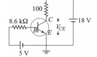
Power gain = (i_c² R_c) / (i_b² R_B) = (i_c/i_b)² (R_c/R_B) = (10²)² (10? /10³) = 10?
i_c/i_b = 100 ⇒ β = i_c/i_b = 100
New answer posted
10 months agoContributor-Level 10
Photodiode operate in reverse bias. The photocurrent increases initially and saturates fi
New answer posted
10 months ago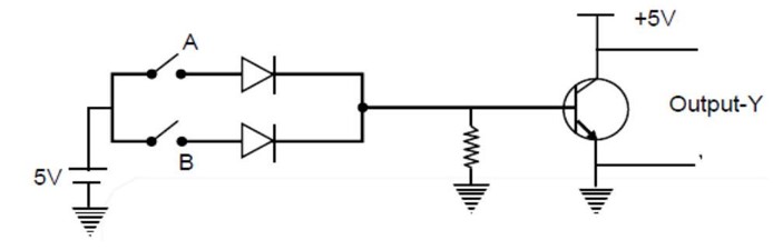
Contributor-Level 9
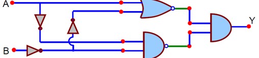
First part of figure shown is or GATE and Second part of figure shown is NOT GATE So, NOR GATE
New answer posted
10 months ago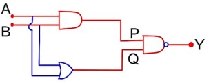
Contributor-Level 9
Input are :
(0, 0) ; (0, 1); (1, 0); (1, 1).
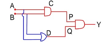
Thus, the output y is : (1, 0) s
A | B | P | Q | Y |
0 | 0 | 0 | 0 | 1 |
0 | 1 | 0 | 1 | 1 |
1 | 0 | 0 | 1 | 1 |
1 | 1 | 1 | 1 | 0 |
New answer posted
11 months ago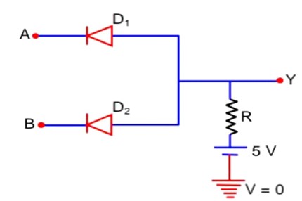
Contributor-Level 10
When both A and B have logical value 'l' both diode are reverse bias and current will flow in resistor hence output will be 5 volt i.e. logical value '1'.
In all other case conduction will take place hence output will be zero value i.e. logical value 'o'.
So truth table is
A B Y
0 0
0 1 0 (AND gate)
1
Taking an Exam? Selecting a College?
Get authentic answers from experts, students and alumni that you won't find anywhere else
Sign Up on ShikshaOn Shiksha, get access to
- 66k Colleges
- 1.2k Exams
- 700k Reviews
- 1850k Answers