
Physics Alternating Current
Get insights from 90 questions on Physics Alternating Current, answered by students, alumni, and experts. You may also ask and answer any question you like about Physics Alternating Current
- 90
Questions
- 0
Discussions
- 0
Active Users
- 5
Followers
Have a question about Physics Alternating Current? Ask our experts
Keep it short & simple. Type complete word. Avoid abusive language.
A 750 Hz, 20 V (rms) source is connected to a resistance of 100Ω, an inductance of 0.1803H and a capacitance of 10µF all in series. The time in which the resistance (heat capacity 2 J/°C) will get heated by 10°C. (assume no loss of heat to the surroundings) is close to:
<!-- [if !supportLineBreakNewLine]-->
<!--[endif]-->
A 750 Hz, 20 V (rms) source is connected to a resistance of 100Ω, an inductance of 0.1803H and a capacitance of 10µF all in series. The time in which the resistance (heat capacity 2 J/°C) will get heated by 10°C. (assume no loss of heat to the surroundings) is close to:
<!-- [if !supportLineBreakNewLine]-->
<!--[endif]-->

An AC circuit has R = 100Ω, C = 2µF and L = 80mH, connected in series. The quality factor of the circuit is:
<!-- [if !supportLineBreakNewLine]-->
<!--[endif]-->
An AC circuit has R = 100Ω, C = 2µF and L = 80mH, connected in series. The quality factor of the circuit is:
<!-- [if !supportLineBreakNewLine]-->
<!--[endif]-->
Q = (1/R)√ (L/C) = (1/100)√ (80e-3/2e-6) = 2
 Upvote

A LCR circuit behaves like a damped harmonic oscillator. Comparing it with a physical spring-mass damped oscillator having damping constant ' ', the connect equivalence would be:
A LCR circuit behaves like a damped harmonic oscillator. Comparing it with a physical spring-mass damped oscillator having damping constant ' ', the connect equivalence would be:
In damped oscillation
In the circuit
Comparing equation (i) and (ii)
Upvote An emf of is applied at time to a circuit containing in series inductor and resistor. The ratio of the currents at time and at is close to: (take
<!-- [if !supportLineBreakNewLine]-->
<!--[endif]-->
An emf of is applied at time to a circuit containing in series inductor and resistor. The ratio of the currents at time and at is close to: (take
<!-- [if !supportLineBreakNewLine]-->
<!--[endif]-->
At
at
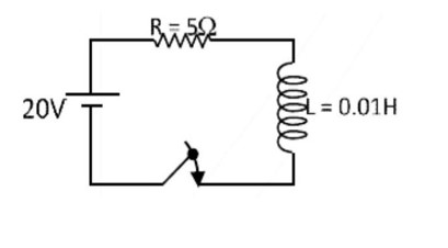
is slightly greater than 1 .
Upvote 
For the given circuit, comment on the type of transformer used.
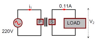
For the given circuit, comment on the type of transformer used.
Voltage across secondary source
P = V? i? = V? i?
V? = P/i? = 60/0.11 ≈ 545 V
Since voltage across secondary source is more than primary source (220V)
⇒ Step- up transformer.
Upvote A 100Ω resistance, a 0.1 µF capacitor and an inductor are connected in series across a 250 V supply at variable frequency. Calculate the value of inductance of inductor at which resonance will occur. Given that the resonant frequency is 60 Hz.
<!-- [if !supportLineBreakNewLine]-->
<!--[endif]-->
A 100Ω resistance, a 0.1 µF capacitor and an inductor are connected in series across a 250 V supply at variable frequency. Calculate the value of inductance of inductor at which resonance will occur. Given that the resonant frequency is 60 Hz.
<!-- [if !supportLineBreakNewLine]-->
<!--[endif]-->
ω = 2πf = 1/√ (LC)
L = 1/ (4π²f²C) = 1/ (4π² * 60² * 0.1*10? ) = 70.3 mH
Upvote Two circuits are shown in the figure (a) & (b). At a frequency of __________ rad /s the average power dissipated in one cycle will be same in both the circuits.
Two circuits are shown in the figure (a) & (b). At a frequency of __________ rad /s the average power dissipated in one cycle will be same in both the circuits.
Power dissipated is same
P? = P?
P_R = P_RLC
(V²/R) = (V²/Z)cos (φ) = (V²/Z) (R/Z) = V²R/Z²
R = R²/Z² => Z² = R²
R² + (ωL - 1/ωC)² = R²
ωL = 1/ωC
ω = 1/√ (LC) = 1/√ (0.1 × 40 × 10? ) = 1/√ (4 × 10? ) = 1/ (2 × 10? ³) = 500 rad/s
Upvote A 0.07 H inductor and a 12Ω resistor are connected in series to a 220 V, 50 Hz ac source. The approximate current in the circuit and the phase angle between current and source voltage are respectively. [Take π as 22/7]
A 0.07 H inductor and a 12Ω resistor are connected in series to a 220 V, 50 Hz ac source. The approximate current in the circuit and the phase angle between current and source voltage are respectively. [Take π as 22/7]
L = 0.07H and R = 12Ω
Vs = 220V, 50Hz
XL = 2πfL = 2 (22/7) (50) (0.07) = 22Ω
Z = √ (R² + XL²) = √ (12² + 22²) = √ (144+484) = √628 ≈ 25Ω
i = V/Z = 220/25 = 8.8A
tan φ = XL/R = 22/12 = 11/6
φ = tan? ¹ (11/6)
Upvote