 / Preparation Physics Alternating Current
Alternating Current (AC) is a type of electrical current in which the flow of electric charge reverses its direction periodically. Alternating current is used in our houses to run electrical appliances like Television, Washing Machine etc.
The other type of electric current is Direct Current or DC. The basic difference between AC and DC lies in the process of creating these currents. In the process of generating Alternating Current, the magnets in the generator move, and the wire/coils are fixed, whereas in generating Direct Current, magnets are fixed, and the wire/coil moves.
Alternating Current is generated at Nuclear power plants, Thermal Power Plants that run through coal, Wind Power Plants, and Water Power Plants as well. The Direct Current is generated usually through Batteries for small/household purposes and through Solar Power Plants for commercial purposes.
- What is Alternating current (AC)
- Alternating Current Definition
- Advantage of AC over DC
- Working Principle of Alternating Current
- Voltage (emf) and Current (I) in the Alternating Current
- Mean or Average Value of AC
- Root Mean Square Value of AC
- Topics Covered in Alternating Current
- Phasors
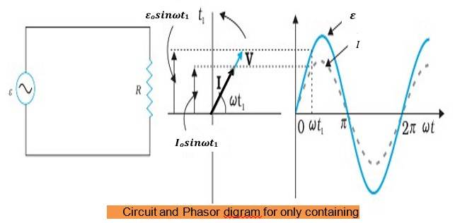
- AC Voltage Applied to a Resistor (R)
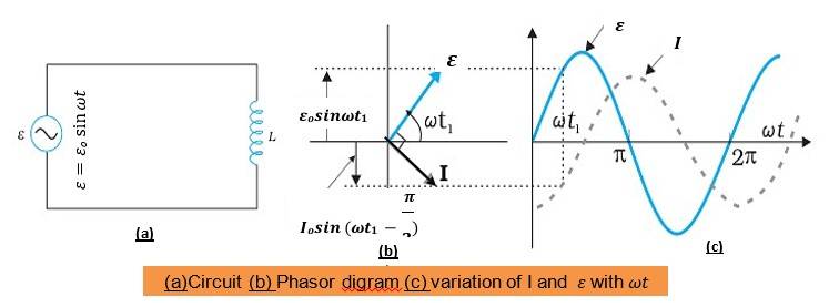
- AC Voltage Applied to an Inductor (L)
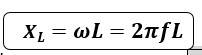
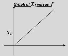
- Inductive Reactance (𝑿𝑳)
- AC Voltage Applied to a Capacitor
- Capacitive Reactance (𝑿𝑪)
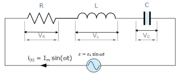
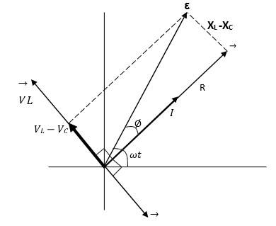
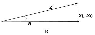
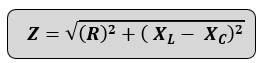
- AC Voltage Applied to a Series LCR Circuit
- Resonance condition of LCR circuit
- Sharpness of resonance: Quality factor
- Power in AC Circuit: The Power Factor
- Power factor(𝒄𝒐𝒔 ∅)
- Analogies Between Mechanical and Electrical Quantities
- Transformer
- Alternating Current Class 12 Physics Chapter 7 Notes
- Alternating Current Important Topics for JEE and NEET
- Practical Application of Alternating Current
What is Alternating current (AC)
Alternating Current is a type of current, the other being DC. An alternating current (AC) reverses direction and changes magnitude over time. It's the type of electricity that's used in homes and businesses to power appliances like fans, lights, and televisions. Before we understand Alternating Current deeply, let's understand what current is.
In the simplest term, electric current or simply current, is the flow of charge through a conductor. The flow of charge happens when there is a potential difference between the positive and negative charge. When an electron moves due to potential difference, the electric charge or electric current is created. The type of electric current created depends on the direction of movement of electron.
When the electron flow changes its direction back and forth, the Alternating current is generated while when the flow of electrons is unidirectional or in a single direction, the Direct Current is produced. We control or generate the AC or DC current through generators with distinctive machinery setup.
Alternating Current Definition
Alternating Current (AC) is a type of electrical current where the flow of electric charge periodically reverses direction. The flow of electrons in AC changes direction at a specific frequency, typically 50 Hz or 60 Hz. AC Current production is based on Faraday's Law of Electromagnetic Induction.
Advantage of AC over DC
Alternating current has high efficiency and no power loss during generation as well as in transmission which makes it the preferred choice for household consumption. Secondly, the cost of generating AC is much lower than DC which makes it cheaper. Also, the voltage of AC and easily be stepped up or down as per the requirements.
Working Principle of Alternating Current
Alternating current is a type of charge in which the flow of charge changes direction with time. But in direct current (DC), the flow of current is steady and in a single direction.
Alternating Current (AC) works on the principle of electromagnetic induction (Faraday's Law).
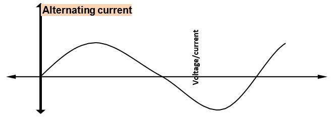
When a coil rotates in the magnetic field, an alternating electromotive force (emf) is produced in the coil. EMF changes its direction as the coil continues to rotate and produce alternating current. The variation in AC is sinusoidal, which means it goes positive and negative in a smooth wave pattern.
Voltage (emf) and Current (I) in the Alternating Current
We know that the source of AC is electric generator as we have seen in EMI topic.
The emf developed is given by,
𝜀 = 𝜀𝑜 sin 𝜔𝑡
Hence current in the circuit is also given by ohm’s law if the R be the resistance of the circuit,
𝐼 = 𝜀/𝑅 = 𝜀𝑜 sin 𝜔𝑡/𝑅
Where, 𝑰 = 𝑰𝒐 𝐬𝐢𝐧 𝝎𝒕 − − − −𝑇ℎ𝑖𝑠 𝑖𝑠 𝑎𝑛 𝑖𝑛𝑠𝑡𝑎𝑛𝑎𝑛𝑒𝑜𝑢𝑠 𝑐𝑢𝑟𝑟𝑒𝑛𝑡 𝑎𝑡 𝑎𝑛𝑦 𝑡𝑖𝑚𝑒 ′𝑡′
𝑰𝒐 =𝜺𝒐/𝑹 − − − 𝑃𝑒𝑎𝑘 𝑜𝑟 𝑚𝑎𝑥𝑖𝑚𝑢𝑚 𝑐𝑢𝑟𝑟𝑒𝑛𝑡 𝑣𝑎𝑙𝑢𝑒 𝑜𝑓 𝐴𝐶
Average value of AC over one complete cycle of AC is ZERO. As alternating current is positive in one half cycle and equally negative in the other half cycle so its mean value over the complete cycle is zero
𝐼 =𝑞/𝑇 = 𝑜
We cannot measure AC by using a simple moving coil galvanometer, it can be measured by using a hot-wire ammeter which is based on the heating effect of current
Mean or Average Value of AC
Mean OR Average value of A.C. is the amount of direct current when passed through a circuit for half the time period of A.C., it sends the same amount of charges through the circuit as sent by the A.C. through same circuit in the same time.
𝑰𝒂𝒗 = 𝑰𝒎 = 𝟐/𝝅 𝑰𝒐 = 𝟎. 𝟔𝟑𝟕 𝑰𝒐
Where, 𝐼𝑜 − 𝑝𝑒𝑎𝑘 𝑣𝑎𝑙𝑢𝑒 𝑜𝑓 𝐴. 𝐶.
Also for emf we can write,
𝜺𝒂𝒗 = 𝜺𝒎 = 𝟐/𝝅 𝜺𝒐 = 𝟎. 𝟔𝟑𝟕 𝜺𝒐
Root Mean Square Value of AC
Root Mean Square(RMS) or Effective value of A.C. is the amount of direct current when passed through a resistor for any duration of a time period, produces the same amount of heat in the resistor as it produced by A.C. in the same resistor in the same time. The amount of energy (heat) produced by rms value of AC will be equal to that of DC for the same time period.
Also for emf we can write,
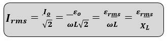
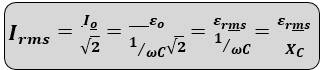
𝑰𝒓𝒎𝒔 𝒐𝒓 𝑰𝒆𝒇𝒇 = 𝑰𝒐/√𝟐 = 𝟎. 𝟕𝟎𝟕 𝑰𝒐
𝜺𝒓𝒎𝒔 𝒐𝒓 𝜺𝒆𝒇𝒇 = 𝜺𝒐/√𝟐 = 𝟎. 𝟕𝟎𝟕 𝜺𝒐
Topics Covered in Alternating Current
Phasors
AC Voltage Applied to a Resistor (R)
AC Voltage Applied to an Inductor (L)
Inductive Reactance (𝑿𝑳)
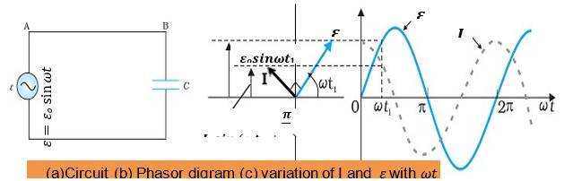
AC Voltage Applied to a Capacitor
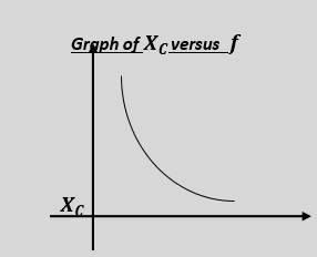
Capacitive Reactance (𝑿𝑪)
AC Voltage Applied to a Series LCR Circuit
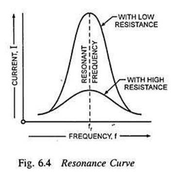
Resonance condition of LCR circuit
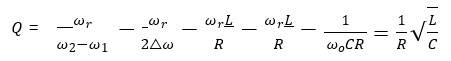
Sharpness of resonance: Quality factor
Power in AC Circuit: The Power Factor
Power factor(𝒄𝒐𝒔 ∅)
Analogies Between Mechanical and Electrical Quantities
Transformer
Alternating Current Class 12 Physics Chapter 7 Notes
Alternating Current Important Topics for JEE and NEET
Practical Application of Alternating Current
Physics Alternating Current Exam
Student Forum
Other Topics under this Chapter
- Coulomb's Law
- Power in AC Circuit
- Representation of AC Current and Voltage by Vector
- AC Voltage applied to a Series LCR circuit
- AC Voltage applied to a Capacitor
- AC Voltage Applied to an Inductor
- AC Voltage Applied to a Resistor
- Alternating Current Overview
- Combination of Resistors - Series and Parallel
- Temperature Dependence of Resistivity
- Potentiometer
- Application of Gauss's law
- Electric Dipole
- Electric Flux
- Gauss Law
Other Class 12th Physics Chapters
- Physics Alternating Current
- Physics Ray Optics and Optical Instruments
- Physics Electromagnetic Induction
- Physics Dual Nature of Radiation and Matter
- Physics Semiconductor Devices
- Physics Wave Optics
- Physics Current Electricity
- Physics Nuclei
- Physics Electrostatic Potential and Capacitance
- Physics Atoms
- Physics Moving Charges and Magnetism
- NCERT Class 12 Notes
- NCERT Class 12 Physics
- Physics Electric Charge and Field
- Physics Electromagnetic Waves
- Physics Magnetism and Matter
Popular Courses After 12th
Exams accepted
CA FoundationExams accepted
ICSI ExamExams accepted
BHU UET | GLAET | GD Goenka TestBachelor of Business Administration & Bachelor of Law
Exams accepted
CLAT | LSAT India | AIBEExams accepted
IPMAT | NMIMS - NPAT | SET
Exams accepted
BHU UET | KUK Entrance Exam | JMI Entrance ExamBachelor of Design in Animation (BDes)
Exams accepted
UCEED | NIFT Entrance Exam | NID Entrance ExamBA LLB (Bachelor of Arts + Bachelor of Laws)
Exams accepted
CLAT | AILET | LSAT IndiaBachelor of Journalism & Mass Communication (BJMC)
Exams accepted
LUACMAT | SRMHCAT | GD Goenka Test