

Class 12th
Get insights from 11.9k questions on Class 12th, answered by students, alumni, and experts. You may also ask and answer any question you like about Class 12th
Follow Ask QuestionQuestions
Discussions
Active Users
Followers
New answer posted
a year agoContributor-Level 10
11.2 Allylic alcohol is an organic compound which has the structural formula CH2 = CHCH2OH. In other words, in these alcohols, the-OH group is attached to sp2 hybridized carbon next to the carbon-carbon double bond, that is to an allylic carbon. Therefore, in the above examples, the following are the allylic alcohols.
(ii) H2C = CH – CH2OH and
New answer posted
a year agoContributor-Level 10
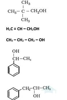
It is primary alcohol because carbon which carries the –OH group is only attached to one alkene group.
It is primary alcohol because the carbon which carries the –OH group is only attached to one propyl group.
It is secondary alcohol because the carbon which carries the –OH group is joined directly to methyl and benzene.
It is secondary alcohol because the carbon which carries the –OH group is joined directly to two different alkyl groups.
New answer posted
a year agoContributor-Level 10
Ferromagnetism: The substances that are strongly attracted by a magnetic field are called ferromagnetic substances can be permanently magnetised even in the absence of a magnetic field. Some examples of ferromagnetic substances are iron, cobalt, nickel, gadolinium, and CrO2. In solid state, the metal ions of ferromagnetic substances are grouped together into small regions called domains and each domain acts as a tiny magnet. In an un-magnetised piece of a ferromagnetic substance, the domains are randomly-oriented and so, their magnetic moments get cancelled. However, when the substance is placed in a magnetic field, all the domains get
New answer posted
a year agoContributor-Level 10
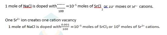
1.49 NaCl is doped with 10−3 mol % of SrCl2
100 moles of NaCl are doped with 0.001 moles of SrCl2
New answer posted
a year agoContributor-Level 10
1.48 It is given that aluminum crystallises in a cubic closed packed structure.
Its metallic radius is 125 pm.
For cubic close-packed structure
a=2√2r=2√2*125=354 pm
Here, a is the edge length of the unit cell and r is the atomic radius.
(ii) Volume of one unit cell = a3 =(354 pm)3=4.4*10−23cm3(1 pm=10−10cm)
Number of unit cells in 1.00cm3= 1.00 cm3 / 4.4*10-23 cm3
= 2.27*1022
New answer posted
a year agoContributor-Level 10
Schottky defect: Schottky defect is basically a vacancy defect shown by ionic solids. In this defect, an equal number of cations and anions are missing to maintain electrical neutrality. It decreases the density of a substance. Significant number of Schottky defects is present in ionic solids. For example, in NaCl, there are approximately 106 Schottky pairs per cm3 at room temperature. Ionic substances containing similar-sized cations and anions show this type of defect. For example: NaCl, KCl, CsCl, AgBr, etc.
Frenkel defect: Ionic solids containing large differences in the sizes of ions show this type of defect. When the smaller ion (
New answer posted
a year agoContributor-Level 10
1.47 The energy gap between the valence band and conduction band in an insulator is very large while in a conductor, the energy gap is very small or there is overlapping between valence band and conduction band.
(ii) In a conductor, the valence band is practically filled or there is overlapping between valence band and conduction band while in semiconductor, there is always a small energy gap between them.

New answer posted
a year agoContributor-Level 10
1.45 For fcc unit cell, a=2√2?.
Here, a is the edge length and r is the atomic radius (0.144 nm).
a = 2√2 *0.144 = 0.407 nm
Hence, the length of a side of a cell is 0.407 nm.
New answer posted
a year agoContributor-Level 10
1.44 Ge is group 14 element and In is group 13 element. Hence an electron deficient hole is created and therefore, it is p–type.
2. B is group 13 elements and Si is group 14 elements, there will be a free electron. Hence, it is n-type
New answer posted
a year agoContributor-Level 10
1.43 There is one octahedral hole for each atom in hexagonal close packed arrangement. If the number of oxide ions (O2−) per unit cell is 1, then the number of

Taking an Exam? Selecting a College?
Get authentic answers from experts, students and alumni that you won't find anywhere else
Sign Up on ShikshaOn Shiksha, get access to
- 66k Colleges
- 1.2k Exams
- 705k Reviews
- 1850k Answers