

Physics Ncert Solutions Class 12th
Get insights from 1.2k questions on Physics Ncert Solutions Class 12th, answered by students, alumni, and experts. You may also ask and answer any question you like about Physics Ncert Solutions Class 12th
Follow Ask QuestionQuestions
Discussions
Active Users
Followers
New answer posted
10 months agoContributor-Level 10
7.17 Inductance of the Inductor, L = 5.0 H
Resistance of the resistor, R = 40 Ω
Capacitance of the capacitor, C = 80 80 F
Potential of the voltage source, V = 230 V
Impedance Z of the given parallel LCR circuit is given as
= where = angular frequency
At resonance = 0 or =
= = 50 rad/s
The magnitude of Z is the maximum at = 50 rad/s. As a result, total current is minimum.
rms current flowing through the Inductor L is given as,
= = = 0.92 A
rms current flowing through the Capacitor C is given as,
= =
New question posted
10 months agoNew answer posted
10 months agoContributor-Level 10
7.16 Capacitance of the capacitor, C = 100 = 100 F
Resistance of the resistor, R = 40 Ω
Supply voltage, V = 110 V
Frequency of the supply voltage, = 12 kHz = 12 Hz
Angular frequency, = 2 = 2 rad/s = 24 rad/s
For a RC circuit, the impedance Z, is given by Z =
Z = = 40 Ω
Peak voltage, = = = 155.56 V
Peak current, = = = 3.8
9 A
In a capacitor circuit, the voltage lags behind the current by a phase angle of . This angle is given by the relation
= =
New answer posted
10 months agoContributor-Level 10
7.15 Capacitance of the capacitor, C = 100 = 100 F
Resistance of the resistor, R = 40 Ω
Supply voltage, V = 110 V
Frequency of the supply voltage, = 60 Hz
Angular frequency, = 2 = 2 rad/s
For a RC circuit, the impedance Z, is given by Z =
Z = = 47.996 Ω
Peak voltage, = = = 155.56 V
Peak current, = = = 3.24 A
In a capacitor circuit, the voltage lags behind the current by a phase angle of . This angle is given by the relation
= = = = 0.663
rad
&n
New answer posted
10 months agoContributor-Level 10
7.14 Inductance of the Inductor, L = 0.50 H
Resistance of the resistor, R = 100 Ω
Potential of supply voltage, V = 240 V
Frequency of the supply, = 10 kHz = 10 Hz
Peak voltage is given as = = 339.41 V
Angular frequency of the supply, = 2
Maximum current in the supply is given as
= = = 10.80 A
Phase angle is also given by the relation,
= = = 314.16
= rad = 1.568 rad
t = = = 24.95 s = 24.95 s
It can be observed that is very small in this case. Hence, at high
New answer posted
10 months agoContributor-Level 10
7.13 Inductance of the Inductor, L = 0.50 H
Resistance of the resistor, R = 100 Ω
Potential of supply voltage, V = 240 V
Frequency of the supply, = 50 Hz
Peak voltage is given as = = 339.41 V
Angular frequency of the supply, = 2
Maximum current in the supply is given as
= = = 1.82 A
Equation for voltage is given as V = and equation for current is given as
I = , where phase difference between voltage and current.
At time t = 0, V = [Maximum voltage condition]
For = 0, I = [ Maximum current condition
New answer posted
10 months agoContributor-Level 10
7.12 Inductance of the Inductor, L = 20 mH = 20 H
Capacitance of the capacitor, C = 50 = 50 F
Initial charge of the capacitor, Q = 10 mC = 10 C
The total energy stored initially at the circuit is given as
E = = = 1 J
Hence, the total energy stored in the LC circuit will be conserved because there is no resistor connected in the circuit.
Natural frequency of the circuit is given by the relation
= = 159.15 Hz
Natural angular frequency, = = 1000 rad/s
(i) Total time period, T = = = 6.28 s = 6.2
New answer posted
10 months ago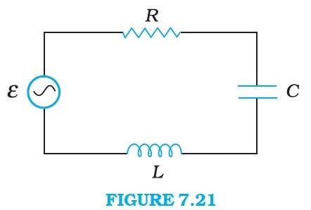
Contributor-Level 10
7.11 Inductance of the Inductor, L = 5.0 H
Resistance of the resistor, R = 40 Ω
Capacitance of the capacitor, C = 80 80 F
Potential of the voltage source, V = 230 V
Resonance angular frequency is given as
= = = 50 rad/s
The impedance of the circuit is given as
Z = where = Inductive reactance and = Capacitive reactance
At resonance, = so Z = R = 40Ω
Amplitude of the current at the resonating frequency is given as
= where = Peak voltage = V
= = = 8.13 A
Hence, at resonance, the
New question posted
10 months agoNew answer posted
10 months agoContributor-Level 10
7.10 Lower tuning frequency, = 800 kHz = 800 Hz
Upper tuning frequency, = 1200 kHz = 1200 Hz
Effective inductance of the circuit, L = 200 = 200 H
Capacitance of variable capacitor for lower tuning frequency ( is given as
= , where is the angular frequency for capacitor = 2
Hence, = 2 800 = 5.026 rad/s
= = F = 1.9789 F = 197.89 pF
Capacitance of variable capacitor for lower tuning frequency ( is given as
= , where &
Taking an Exam? Selecting a College?
Get authentic answers from experts, students and alumni that you won't find anywhere else
Sign Up on ShikshaOn Shiksha, get access to
- 66k Colleges
- 1.2k Exams
- 687k Reviews
- 1800k Answers