 / Preparation Physics Wave Optics
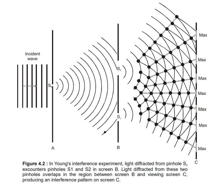
Thomas Young was the first one who demonstrated the double-slit experiment in the year 1801. The expirement showed that light must behave like a wave rather than a particle. He passed sunlight through a single slit to produce a coherent beam, then through two closely spaced slits, creating two overlapping wavefronts. On a distant screen, these overlapping waves produced alternating bright and dark fringes—an interference pattern that cannot be explained by a stream of particles . The bright fringes occurred where waves from both slits arrived in phase and reinforced each other, while dark fringes resulted from waves arriving out of phase and canceling. By blocking one of the slits, Young showed that the pattern disappeared. This proved that both the slits were required for creating the wave-like fringes.
Do note that NCERT solutions of Wave optics must be practiced by students before sitting for CBSE board or any other enterance examination.
- Young's Double Slit Experiment (Y.D.S.E.)
- Analysis of Interference Pattern
- Fringe width
- Maximum order of Interference Fringes
- Intensity
- Derivation of Young's Double Slit Experiment
Young's Double Slit Experiment (Y.D.S.E.)
Thomas Young came up with a technique in 1802, which created a stationary interference pattern. A single wavefront was divided into two, and these two wavefronts appeared to be coming from two sources with a stable phase connection. This resulted in a steady interference pattern when they were let to interfere and called Young's Double Slit Experiment.
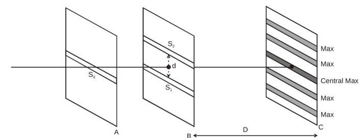
Figure : 4.1 : Young's Arrangement to produce stationary interference pattern by division of wave front into and
This is an important concepts considering JEE Mains exam and NEET exam since 2 questions were asked in the last year paper carrying a total weightage of 8 marks.
Analysis of Interference Pattern
In the configuration above, we have guaranteed that the light waves traveling through and are in phase. However, since the wave from must take a longer route to reach P than the wave from , the waves may not be in phase when they arrive at from . The path difference-induced phase difference has already been covered. The arriving waves experience constructive interference and are precisely in phase if the path difference is zero or an integral multiple of wavelengths. Arriving waves that have a route difference that is an odd multiple of half a wavelength are out of phase and experience completely destructive interference. Therefore, the intensity at a point is determined by the path difference Δx.
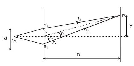
Path difference
Approximation I : For D >> d, we can approximate rays
and 2 as being approximately parallel, at angle
to the principle axis.
Now,
path difference

Approximation II : Further if
is small, i.e.,
and hence, path difference
for maxima (constructive interference),
Here
corresponds to the central maxima
correspond to the 1st maxima
correspond to the 2 nd maxima and so on.
for minima (destructive interference).
consequently,
Here
corresponds to first minima,
corresponds to second minima and so on.
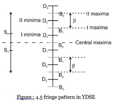
Fringe width
It is the distance between two maxima of successive order on one side of the central maxima. This is also equal to distance between two successive minima.
fringe width
Notice that it is directly proportional to wavelength and inversely proportional to the distance between the two slits.
Maximum order of Interference Fringes
In section 4.1 we obtained,
.
for interference maxima, but n cannot take infinitely large values, as that would violate the approximation (II) i.e.,
is small or
Hence the above formula (
) for interference maxima/minima are applicable when
when becomes comparable to path difference can no longer be given by equation (4.3) but by (4.2) Hence for maxima
Hence highest order of interference maxima,
where [ ] represents the greatest integer function.
Similarly highest order of interference minima,
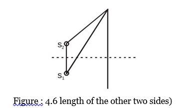
Alter
(3rd side of a triangle is always greater than the difference in
Intensity
Suppose the electric field components of the light waves arriving at point
(in the Figure : 4.3) from the two slits
and
vary with time as
and
Here
and we have assumed that intensity of the two slits
and
are same (say
); hence waves have same amplitude E.
then the resultant electric field at point
is given by,
where
Hence the resultant intensity at point
,
when .
Here
If
If
However if the two slits were of different intensities
and
,
say
and
then resultant field at point P ,
where
Hence resultant intensity at point P ,
Derivation of Young's Double Slit Experiment
Suppose there is a glass slab that has a refractive index μ and t thickness. Say, this glass is placed in the way of one of the interfering waves. In this case, the optical length of this path will be μ, which will rise by (t-1) μ. Through this, the path difference will be Δx = μt – t = (μ-1)t
In case, the present location of fringe is y =D/d (Δx); then new position of the fringe will be
y’ = D/d(Δx + (μ-1)t).
where
D: The distance from the lens to the image plane (or screen).
d: The distance from the lens to the object (or the source plane).
Therefore, Fringe lateral shift will be y₀ = y’ – y
y₀ = D/d(μ-1)t
Fringe width, w = D/dλ
So, we will get
y₀ = β/λ (μ-1)t
Physics Wave Optics Exam
Student Forum
Other Class 12th Physics Chapters
- Physics Alternating Current
- Physics Ray Optics and Optical Instruments
- Physics Electromagnetic Induction
- Physics Dual Nature of Radiation and Matter
- Physics Semiconductor Devices
- Physics Wave Optics
- Physics Current Electricity
- Physics Nuclei
- Physics Electrostatic Potential and Capacitance
- Physics Atoms
- Physics Moving Charges and Magnetism
- NCERT Class 12 Notes
- NCERT Class 12 Physics
- Physics Electric Charge and Field
- Physics Electromagnetic Waves
- Physics Magnetism and Matter