 / Preparation Physics Electromagnetic Induction
The main objective of this article is to offer you an in-depth conceptual understanding of the electromagnetic interaction between two parallel current-carrying conductors. The electric charge is the foundation for all electromagnetic phenomena.
As discussed in class 12 physics electrostatics, a static electric charge produces an electric field, and the electric field exerts a force on other nearby charges. The story changes when a charge is in any form of motion.
Similarly, a moving charge produces a magnetic field and experiences a magnetic force when placed in a magnetic field. This is why when two conductors are placed parallel to each other, both exert equal and opposite magnetic forces on each other.
French physicist André-Marie Ampère also gave the standard definition of ampere in terms of the magnitude of force between parallel conductors carrying 1 ampere current. This topic is very important for CBSE Class 12 physics and JEE exam. You can get a direct numerical problem or a theoretical question based on this concept. You can practice NCERT problems and analyse using Shiksha's NCERT Solutions for complete preparation of the topic.
- Force Between Two Parallel Current Carrying Conductor
- Right Hand Thumb Rule: Direction of Force
- Biot-Savart Law: Magnetic Field Due to Current Carrying Conductor
- Magnetic Force on a Current Carrying Conductor in a Field
- NCERT Derivation: Magnetic Force Between Two Parallel Current Carrying Conductor
- Solved Examples: Force Between Two Parallel Current Carrying Conductor
- NCERT Physics Class 12 Chapters
- Complete Class 12 Study Material for CBSE Exams
Force Between Two Parallel Current Carrying Conductor
Before getting into the details of magnetic force, a crystal clear understanding of the chronology of events is necessary.
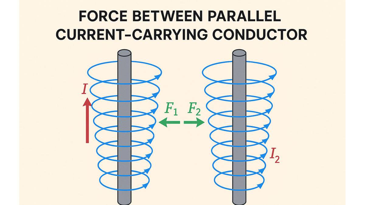
How does a current-carrying wire exert force?
The Biot-Savart law explains that any current-carrying conductor generates a magnetic field around it. The magnetic field depends on several factors, such as the amount of current, the distance from the wire, the length of the wire, and the angle between the current element and the position vector.
Since both wires are carrying current, that means both will produce a magnetic field around themselves. The magnetic interaction between wires allows both wires to exert force on each other.
According to the Lorentz Force, the force on a current-carrying conductor due to a magnetic field can be expressed as;
The force experienced by a straight wire of length L, carrying current I in a magnetic field B:
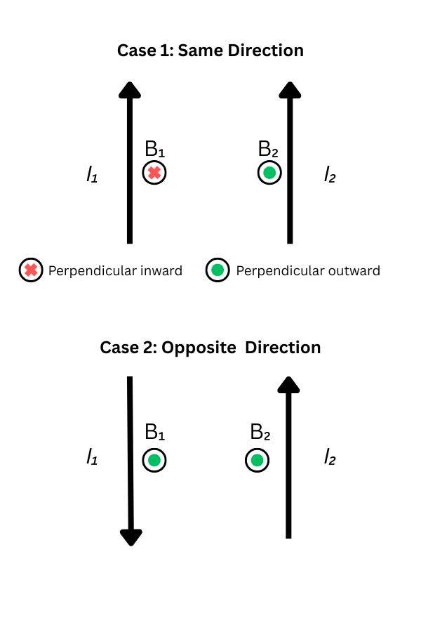
There are two cases when wires are carrying parallel currents to each other.
- Case 1 (Repulsive Force): The direction of flow of current is in the same direction in both wires.
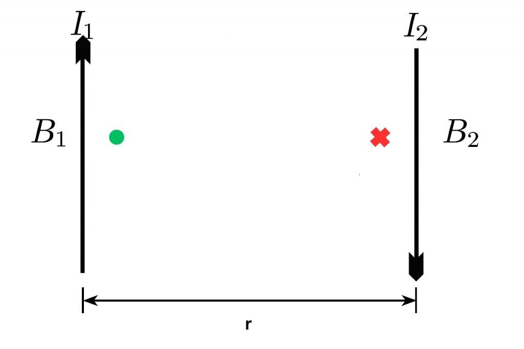
- Case 2 (Attractive Force): The flow of current is in opposite directions to each other in the wires.
We know the formula for the Magnetic field due to a straight current-carrying conductor.
So, the magnitude of the magnetic force on wire 1 due to the magnetic field generated due to wire 2, when the distance between wires is r,
The force per unit length on any of the wires is;
Where;
μ₀ = permitivity of space.
Two key concepts to understand the method to derive the magnetic forcce between two parallel conductors carrying current.
- Right-hand Thumb Rule: The direction of Magnetic Field generated around the wire.
- Biot-Savart Law: The magnitude Magnetic Field generated around the wire.
Right Hand Thumb Rule: Direction of Force
The Ampère’s right-hand grip rule is one of the easiest methods to find the direction of the magnetic field due to a current-carrying wire. What you need is just the direction of the flow of current.
As per the NCERT Textbooks, "Imagine that you are holding a current-carrying straight conductor in your right hand such that the thumb points towards the direction of current. Then your fingers will wrap around the conductor in the direction of the field lines of the magnetic field." This is known as the right hand thumb rule.

Know more about the right-hand thumb rule through the Wikipedia article on right-hand rule: Right-hand Rule
Biot-Savart Law: Magnetic Field Due to Current Carrying Conductor
As per the NCERT textbooks," According to Biot-Savart’s law, the magnitude of the magnetic field dB is proportional to the current I, the element length dl, and inversely proportional to the square of the distance r. Its direction is perpendicular to the plane
containing dl and r."
Where:
-
= magnetic field element
-
= permeability of free space
-
= current
-
= infinitesimal length vector element of conductor.
-
= distance between current element and point.
Now for a straight current carrying conductor, using biot-savart law the magnetic field expression:
Magnetic Force on a Current Carrying Conductor in a Field
To calculate the magntic force on a current carrying conductor due to a magnetic field we must know the lorentz force formula. The Lorentz force provides specific formula which gives the magnitude of the actual magnetic force experienced.
The mathematical expression of lorentz force on a current-carrying conductor;
F=ILBsinθ
Where:
L = Length of the conductor
θ = Angle between current (direction) and magnetic field
.
NCERT Derivation: Magnetic Force Between Two Parallel Current Carrying Conductor
To derive the formula of the magnetic force between two parallel current-carrying conductors, we need to start with the magnetic field due to a straight wire.
Using Ampère's law for a closed circular loop of radius r around a long straight wire carrying current . Since the magnetic field is tangential and constant on the loop, so
Since the Lorentz force on a moving charge
If this charge is flowing through a wire, considering wire 1 and wire 2, with cross-sectional area , charge carrier density , each carrier charge , and drift velocity .
The total charge flowing through the wire in unit time: .
So, Net magnetic force on total charge:
Since current is charge passing per unit time, So
Substitute
The force per unit length:
Solved Examples: Force Between Two Parallel Current Carrying Conductor
Q.A square coil of side 10 cm consists of 20 turns and carries a current of 12 A. The coil is suspended vertically and the normal to the plane of the coil makes an angle of 30º with the direction of a uniform horizontal magnetic field of magnitude 0.80 T. What is the magnitude of torque experienced by the coil?
Length of a side of the square coil, l = 10 cm = 0.1 m
Current flowing through the coil, I = 12 A
Number of turns of the coil, n = 20
Angle made by the plane of the coil with magnetic field, = 30
Strength of the magnetic field, B = 0.80 T
Magnitude of the magnetic torque experienced by the coil in the magnetic field is given by,
= nBIA, where A = Area of the square coil = 0.1
= 0.96 Nm
Q. Answer the following questions: (a) A magnetic field that varies in magnitude from point to point but has a constant direction (east to west) is set up in a chamber. A charged particle enters the chamber and travels undeflected along a straight path with constant speed. What can you say about the initial velocity of the particle? (b) A charged particle enters an environment of a strong and non-uniform magnetic field varying from point to point both in magnitude and direction, and comes out of it following a complicated trajectory. Would its final speed equal the initial speed if it suffered no collisions with the environment? (c) An electron travelling west to east enters a chamber having a uniform electrostatic field in north to south direction. Specify the direction in which a uniform magnetic field should be set up to prevent the electron from deflecting from its straight line path.
- The initial velocity of the particle is either parallel or anti-parallel to the magnetic field. Hence, it travels along a straight path without suffering any deflection in the field.
- Yes, the final speed of the particle will be equal to its initial speed. This because magnetic force can change the direction of velocity, not its magnitude.
- This moving electron can remain undeflected if the electric force acting on it is equal and opposite of magnetic field. Magnetic force is directed towards the south. According to Fleming’s left hand rule, magnetic field should be applied in a vertically downward direction.
Q. The wires which connect the battery of an automobile to its starting motor carry a current of 300 A (for a short time). What is the force per unit length between the wires if they are 70 cm long and 1.5 cm apart? Is the force attractive or repulsive?
Current in both the wires, I = 300 A
Distance between the wires, r = 1.5 cm = 0.015 m
Length of the two wires, l = 70 cm = 0.7 m
Now, force between the two wires is given by the relation:
F = , where = Permeability of free space = 4 T m
Hence F = N/m = 1.2 N/m
Since the direction of the current in the wires is opposite, a repulsive force exists between them.
Q.4.23 A uniform magnetic field of 1.5 T exists in a cylindrical region of radius10.0 cm, its direction parallel to the axis along east to west. A wire carrying current of 7.0 A in the north to south direction passes through this region. What is the magnitude and direction of the force on the wire if, (a) the wire intersects the axis, (b) the wire is turned from N-S to northeast-northwest direction, (c) the wire in the N-S direction is lowered from the axis by a distance of 6.0 cm?
Magnetic field strength, B = 1.5 T
Radius of the cylindrical region, r = 10 cm = 0.1 m
Current in the wire passing through the cylindrical region, I = 7 A
- If the wire intersect the axis, then the length of the wire is the diameter of the cylindrical region, then l = 2r = 0.2 m
Angle between the magnetic field,
Magnetic force acting on the wire is given by the relation,
F = BIl = 1.5 = 2.1 N
Hence, a force of 2.1 N acts on the wire in a vertically downward direction.
- If the wire is turned from N-S to NE-NW direction, new length of the wire can be given as
Angle between magnetic field and current = 45
Force on the wire,
F = BI = BIl = 1.5 0.2 = 2.1 N
A vertically downward force of 2.1 N acts on the wire.
- When the wire is lowered from the axis by distance, d = 6.0 cm = 0.06 m
Let be the new length and is given by
= 4 (d + r) = 4(6 + 10) = 64
16 cm = 0.16 m
= BI = 1.5 = 1.68 N
The force acts vertically downwards.
NCERT Physics Class 12 Chapters
Here we have provided the NCERT Class 12 notes.
| Sl. No |
Name of Chapter |
|---|---|
| 1 |
Chapter 1: Electric Charges and Fields |
| 2 |
|
| 3 |
|
| 4 |
|
| 5 |
Chapter 5: Magnetism and Matter |
| 6 |
|
| 7 |
|
| 8 |
|
| 9 |
|
| 10 |
|
| 11 |
|
| 12 |
|
| 13 |
Chapter 13: Nuclei |
| 14 |
Chapter 14: Semiconductor Electronics: Materials, Devices and Simple Circuits |
Complete Class 12 Study Material for CBSE Exams

Commonly asked questions
What is the formula for the force per unit length between two parallel current-carrying conductors?
The exact formula for the magnetic force per unit length between two parallel current-carrying conductors:
For more information, check: Force between parallel conductors
How does the force between parallel conductors used in defining the ampere (current SI unit)?
The "ampere" was defined based on the magnetic interaction. The scientific community used the magnetic force between two parallel current-carrying conductors placed at a distance. Below is the definition of 1 ampere, based on this concept.
1 Ampere is the constant current that produces a magnetic force of exactly when two infinitely long, straight, parallel conductors are placed one meter apart in vacuum. |
What is the direction of the force between two parallel current-carrying conductors?
The direction of the net magnetic force is always perpendicular to the plane of current-carrying conductors. The direction of the magnetic force is determined through the right-hand rule.
The right-hand thumb rule states that if you wrap a wire in a way that the thumb points towards the flow of current. Then your curled fingers represent the direction of the field lines of the magnetic field
Physics Electromagnetic Induction Exam
Student Forum
Other Topics under this Chapter
- Experiments of Faraday and Henry
- Motional Electromotive Force
- Combination of Capacitors
- Parallel Plate Capacitor
- Electrostatics of Conductors
- Electromagnetism
- Torque on current loop, magnetic loop dipole
- Moving Coil Galvanometer
- Force between two parallel currents, the Ampere
- The Solenoid and the Toroid
- Magnetic Force
- Planck Equation
- Curie Weiss Law
- Electromotive Force
- Magnetic Effect of Electric Current
Other Class 12th Physics Chapters
- Physics Alternating Current
- Physics Ray Optics and Optical Instruments
- Physics Electromagnetic Induction
- Physics Dual Nature of Radiation and Matter
- Physics Semiconductor Devices
- Physics Wave Optics
- Physics Current Electricity
- Physics Nuclei
- Physics Electrostatic Potential and Capacitance
- Physics Atoms
- Physics Moving Charges and Magnetism
- NCERT Class 12 Notes
- NCERT Class 12 Physics
- Physics Electric Charge and Field
- Physics Electromagnetic Waves
- Physics Magnetism and Matter
Popular Courses After 12th
Exams accepted
CA FoundationExams accepted
ICSI ExamExams accepted
BHU UET | GLAET | GD Goenka TestBachelor of Business Administration & Bachelor of Law
Exams accepted
CLAT | LSAT India | AIBEExams accepted
IPMAT | NMIMS - NPAT | SET
Exams accepted
BHU UET | KUK Entrance Exam | JMI Entrance ExamBachelor of Design in Animation (BDes)
Exams accepted
UCEED | NIFT Entrance Exam | NID Entrance ExamBA LLB (Bachelor of Arts + Bachelor of Laws)
Exams accepted
CLAT | AILET | LSAT IndiaBachelor of Journalism & Mass Communication (BJMC)
Exams accepted
LUACMAT | SRMHCAT | GD Goenka Test