 / Preparation Physics Alternating Current
- What is a Series Circuit?
- What is a Parallel Circuit?
- Applications of Series and Parallel Circuits
- Series and Parallel for Class 10
- FAQs
What is a Series Circuit?
A series circuit is a circuit when the current flows in the same direction in all the circuit components. In this type of circuit, there is only one way for the current to pass. It is more like the connection of bulbs in a single row flowing through the same channel. If one of the bulbs in the series fuses, the whole series won’t light up.
Properties –
- The current flows singly.
- The supply voltage is equal to the sum of all the individual voltages of the resistance.
V = V1 + V2 + V3 + V4 ……., + Vn
- Individual resistance is equal to the equivalent resistance.
- The formula of the same is:
R > R1, R > R2 ……., R > Rn
What is a Parallel Circuit?
A parallel circuit is the opposite of a series circuit. In parallel series, the current has multiple directions to flow. If one bulb fuses, others won’t fuse, they keep on lighting because the current is flowing in various directions. In a parallel circuit, the voltage is divided and flows in all directions.
Properties –
- The current in a parallel circuit flows in different directions.
- The total gets equally distributed in the multiple channels of the circuit.
- the formula is derived by adding all the individual resistances of the circuit which is shown below:
I = I1 + I2 + I3 + ……+ In
- The resistances are also different in parallel circuits because of multiple channels of current. The formula of the resistance of the parallel circuit is:
R < R1, R < R2, ….., R < Rn
Diagrammatic Representation of Series and Parallel Circuit Resistors:
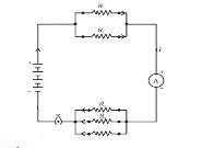
Image source: ncert
The above diagram shows the combination of series and parallel resistors. From the diagram, we can see that the current in a series circuit is flowing through one channel, whereas a parallel circuit current has multiple ways to flow. One of the biggest disadvantages of a series circuit is that if one bulb fuses, the whole series will fuse and won’t work.
Applications of Series and Parallel Circuits
A couple of applications of series and parallel circuits are listed below:
- Series circuit is mostly used in decorative lights and batteries, where multiple cells are connected, and current flows in one direction.
- The following formula can explain parallel circuit’s total resistance:
1/Rtotal = 1/Ra + 1/Rb + ... 1/Rn.
Series and Parallel for Class 10
The chapter on ‘Electricity/Electric Circuit’ holds a significant weightage of 7 marks. This chapter is considered one of the most important in physics because it consists of a long question (5 marks) and two objective type questions of 1 mark each.
Illustrated Examples
- Present an illustration for the parallel circuit.

Image source: ncert
- Explain a few properties of a parallel circuit.
The current in a parallel circuit flows in different directions. The total gets equally distributed in the multiple channels of the circuit.
- Provide a real-world application example of parallel and serial circuit
The series circuit is mostly used in decorative lights and batteries, where multiple cells are connected, and the current flows in one direction.
FAQs
Q; (a) Three resistors 2 Ω, 4 Ω and 5 Ω are combined in parallel. What is the total resistance of the combination? (b) If the combination is connected to a battery of emf 20 V and negligible internal resistance, determine the current through each resistor, and the total current drawn from the battery.
A: Let R1= 2 Ω, R2= 4 Ω, R3= 5 Ω
If the equivalent resistance is R, then 1/R = 1/R1 + 1/R2 + 1/R3 = 1/2 + 1/4 + 1/5 = 10+5+4/20 = 19/20
R = 20/19 = 1.05 Ω
- (b) The EMF of the battery = 20 V
Current through R1, I1 = V/R1 = 20/2 = 10 A
Current through R2, I2 = V/R2 = 20/4 = 5A
Current through R3, I3 = V/R3 = 20/5 = 4 A
Total current I = I1 + I2 + I3 = 10 + 5 + 4 = 19 A
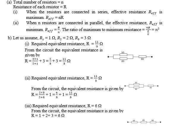
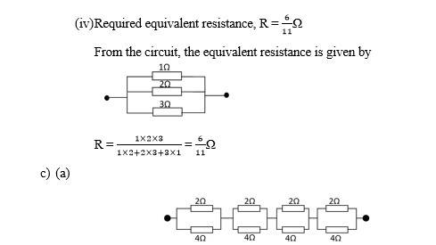
Q: (a) Given n resistors each of resistance R, how will you combine them to get the (i) maximum (ii) minimum effective resistance? What is the ratio of the maximum to minimum resistance? (b) Given the resistances of 1 Ω, 2 Ω, 3 Ω, how will be combine them to get an equivalent resistance of (i) (11/3) Ω (ii) (11/5) Ω, (iii) 6 Ω, (iv) (6/11) Ω? (c) Determine the equivalent resistance of networks shown in Fig. 3.31.
A:
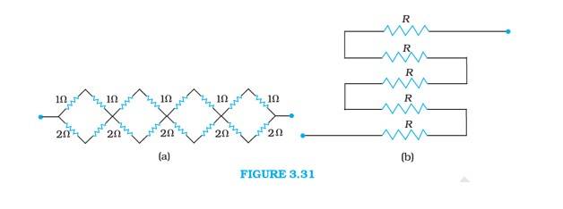
It can be observed from the given circuit that in the first small loop, two resistors of resistance 1 Ω each are connected in the series. Hence the equivalent resistance is = 1 + 1= 2 . At the bottom part 2 resistors of 2 Ω each are connected in a series and thus make equivalent resistance of 2 + 2 = 4 Ω. Thus the circuit can be redrawn as 2 Ω and 4 Ω resistances are connected in parallel. Hence the equivalent resistance of each loop is R = = Ω. All these 4 loop resistors are connected in series. Thus the total equivalent resistance is Ω Ω
- Here all 5 resistors are connected in series. So the equivalent resistance is
5
Q: Name two different types of circuits.
A: Parallel circuit and serial circuit.
Q: What’s the name of the theorem which has the objective of replacing a complex of structures with a voltage source and resistance?
A: Thevenin theorem.
Q: What do you call the current flowing through an unloaded voltage divider?
A: The term known to define this phenomenon is Bleeder current.
Q: What would be the total resistance if the voltage divider is connected to the load?
A: The total resistance will decrease.
Q: Explain one property of a serial circuit.
A: The current flows singly.
Physics Alternating Current Exam
Student Forum
Other Topics under this Chapter
- Gauss Law
- Transformer
- Kirchhoff's Law
- Electric Charge
- NEET Questions
- Unit of Equivalent Conductivity
- Unit of Specific Conductivity
- Series and Parallel
- Half Wave Rectifier Diagram
- Electric Potential due to a point charge
- Heating Effect of Electric Current
- Superposition Principle
- Difference between AC and DC
- Unit of Molar Conductivity
- Electron Drift Velocity
Other Class 12th Physics Chapters
- Physics Alternating Current
- Physics Ray Optics and Optical Instruments
- Physics Electromagnetic Induction
- Physics Dual Nature of Radiation and Matter
- Physics Semiconductor Devices
- Physics Wave Optics
- Physics Current Electricity
- Physics Nuclei
- Physics Electrostatic Potential and Capacitance
- Physics Atoms
- Physics Moving Charges and Magnetism
- NCERT Class 12 Notes
- NCERT Class 12 Physics
- Physics Electric Charge and Field
- Physics Electromagnetic Waves
- Physics Magnetism and Matter
Popular Courses After 12th
Exams accepted
CA FoundationExams accepted
ICSI ExamExams accepted
BHU UET | GLAET | GD Goenka TestBachelor of Business Administration & Bachelor of Law
Exams accepted
CLAT | LSAT India | AIBEExams accepted
IPMAT | NMIMS - NPAT | SET
Exams accepted
BHU UET | KUK Entrance Exam | JMI Entrance ExamBachelor of Design in Animation (BDes)
Exams accepted
UCEED | NIFT Entrance Exam | NID Entrance ExamBA LLB (Bachelor of Arts + Bachelor of Laws)
Exams accepted
CLAT | AILET | LSAT IndiaBachelor of Journalism & Mass Communication (BJMC)
Exams accepted
LUACMAT | SRMHCAT | GD Goenka Test