 / Preparation Physics Alternating Current
Have you ever noticed why the voltage is the same every time? Neither high nor low. Sometimes there may be fluctuation; otherwise, they remain the same for the rest of the time. The stability of the electrical system is made possible by devices like transformers. A transformer is a device that converts the AC voltage without changing its frequency.
A transformer is an important concept in CBCSE Class 12 Physics. It is noticed that a question based on a transformer is asked in the exam. So students must focus on this topic.

- What is a transformer?
- Construction of Transformer
- Working Principle of Transformer
- Transformer EMF Equation
- Types of Transformers
- Ideal Transformer
- Energy Loss in Transformers
- Application of Transformer
- NCERT Notes for Class 12 Physics
- Class 12 Physics NCERT Solutions
- FAQs on Basic Properties of Charge
What is a transformer?
We can define a transformer as an electrical device that transforms the AC voltage without changing its frequency. It works on the principle of mutual induction. There are mainly two types of transformers: step-up transformers and step-down transformers.
Related Topics:
| NCERT Class 12 notes | |
| Maths Class 12 NCERT notes |
Construction of Transformer
To construct a transformer, we need a laminated iron core and a copper wire. Moreover, insulation and cooling systems are also integral to ensure safe and efficient operation. Let's discuss the components of a transformer below:
Core
Earlier, an iron core was used in a transformer. Now in modern transformers, we use laminated silicon steel cores, because they reduce the energy loss, such as hysteresis loss and eddy current loss. The silicon steel minimizes the energy loss and provides a path for magnetic flux. The shape of the core is E-I or toroidal.
Copper Wire
There are two sets of wires in a transformer: primary and secondary. We use copper wire because it is a good conductor of electricity. The wire is wound around the iron core.
The primary winding is connected to the input voltage source, and the secondary winding is connected to the output.
When current passes through the primary coil, a magnetic field is produced in the core. The magnetic field generates a voltage in the secondary winding.
Also Read:
Working Principle of Transformer
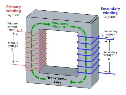
A transformer works on the principle of mutual induction of two coils or Faraday’s Law of Electromagnetic induction. When the current in the primary coil is changed, the flux linked to the secondary coil also changes. Hence, an EMF is induced in the secondary coil due to Faraday’s law of electromagnetic induction. The equations of the transformer working principle PDF are given below
Then the induced emf in the second coil is given by,
𝑑∅
𝜀𝑠 = −𝑁𝑠 𝑑𝑡 − − − (1)
Also, the induced back emf in the primary coil is given by,
𝑑∅
𝜀𝑃 = −𝑁𝑃 𝑑𝑡 − − − (2)
Dividing equations (1) and (2,) we get
𝜀𝑃=𝑁𝑠𝑁𝑃 (∵𝜀𝑠=𝑉𝑠 𝑎𝑛𝑑 𝜀𝑃=𝑉𝑃) 𝑉𝑠/𝑉𝑃=𝑁𝑠/𝑁𝑃−−−(3)
If there is no loss of energy while transforming, then there is no loss of energy, then
Input power = Output power
𝑃𝑖𝑛𝑝𝑢𝑡 = 𝑃𝑜𝑢𝑡𝑝𝑢𝑡
𝐼𝑃𝑉𝑃 = 𝐼𝑆𝑉𝑆
From (3) and (4),
𝑉𝑠
𝑉𝑃
𝐼𝑃 = 𝐼𝑆
− − − −(4)
| 𝑰𝑷 = 𝑽𝒔 = 𝑵𝒔 𝑰𝑺 𝑽𝑷 𝑵𝑷 |
Transformer EMF Equation
The EMF equation helps to explain the relationship between the voltage, frequency, number of turns and magnetic flux in a transformer. The electromotive force (EMF) equation is:
where:
- is the electromotive force (EMF) produced in volts
- is the frequency of AC supply in hertz (Hz)
- is the number of turns in the winding
- is the maximum flux in the core in webers (WB).
Important Links:
| NCERT Class 11 notes | |
| Chemistry Class 11 notes |
Types of Transformers
There are mainly two types of transformers:
- Step-up transformer
- Step-down transformer
Step-up Transformer
We use a step-up transformer when a high voltage output is required. A step-up transformer converts low voltage to high voltage. We get high voltage when the number of turns in the secondary coil is more than the number of turns in the primary coil ( Np < NS ).
Step-down transformer:
A step-down transformer converts high voltage to low voltage. For this step up, the number of turns in the primary coil is more than the number of turns in the secondary coil (Np > NS).
| Step-up Transformer 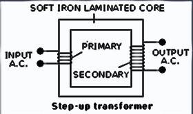
|
Step-down transformer 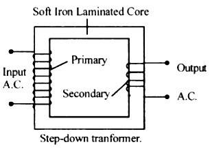
|
Ideal Transformer
An ideal transformer is linear, lossless and perfectly coupled. Perfect coupling implies infinitely high core magnetic permeability and winding inductance and zero net magneto motive force (i.e. ipnp − isns = 0).
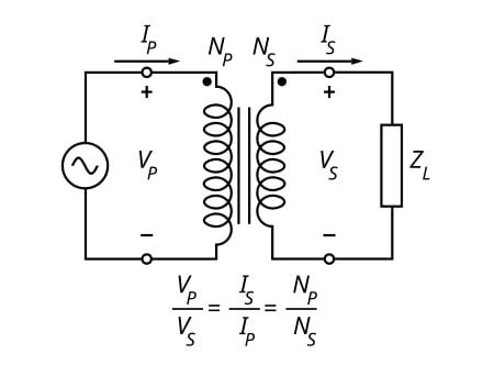
Ideal transformer connected with source VP on primary and load impedance ZL on secondary, where 0 < ZL < ∞.
Energy Loss in Transformers
Transformer energy losses are dominated by winding and core losses. Transformers' efficiency tends to improve with increasing transformer capacity. The efficiency of typical distribution transformers is between about 98 and 99 per cent. In transformers, small energy losses do occur due to the following reasons
- Copper loss
- Eddy current loss
- Hysteresis loss
- Flux leakage
- Humming loss
Application of Transformer
NCERT Notes for Class 12 Physics
Class 12 Physics NCERT Solutions
FAQs on Basic Properties of Charge
Physics Alternating Current Exam
Student Forum
Other Topics under this Chapter
- Combination of Resistors - Series and Parallel
- Temperature Dependence of Resistivity
- Potentiometer
- Application of Gauss's law
- Electric Dipole
- Electric Flux
- Gauss Law
- Transformer
- Kirchhoff's Law
- Electric Charge
- NEET Questions
- Unit of Equivalent Conductivity
- Unit of Specific Conductivity
- Series and Parallel
- Half Wave Rectifier Diagram
Other Class 12th Physics Chapters
- Physics Alternating Current
- Physics Ray Optics and Optical Instruments
- Physics Electromagnetic Induction
- Physics Dual Nature of Radiation and Matter
- Physics Semiconductor Devices
- Physics Wave Optics
- Physics Current Electricity
- Physics Nuclei
- Physics Electrostatic Potential and Capacitance
- Physics Atoms
- Physics Moving Charges and Magnetism
- NCERT Class 12 Notes
- NCERT Class 12 Physics
- Physics Electric Charge and Field
- Physics Electromagnetic Waves
- Physics Magnetism and Matter
Popular Courses After 12th
Exams accepted
CA FoundationExams accepted
ICSI ExamExams accepted
BHU UET | GLAET | GD Goenka TestBachelor of Business Administration & Bachelor of Law
Exams accepted
CLAT | LSAT India | AIBEExams accepted
IPMAT | NMIMS - NPAT | SET
Exams accepted
BHU UET | KUK Entrance Exam | JMI Entrance ExamBachelor of Design in Animation (BDes)
Exams accepted
UCEED | NIFT Entrance Exam | NID Entrance ExamBA LLB (Bachelor of Arts + Bachelor of Laws)
Exams accepted
CLAT | AILET | LSAT IndiaBachelor of Journalism & Mass Communication (BJMC)
Exams accepted
LUACMAT | SRMHCAT | GD Goenka Test