 / Preparation Physics Ncert Solutions Class 12th
In Chapter 6 of Class 12 physics, NCERT explains that a simple change in the magnetic flux leads to the generation of an electric field. This induced electric field creates a voltage difference between the two ends of the conductor, and alternating current is a result of the alternating voltage difference.

This page is a compilation of the best study material related to alternating current. Before accessing the NCERT Solutions, use the chapter-specific resources like quick notes, formulas, and important topics. Also, access the free PDF of Chapter 7 NCERT Solutions of Class 12 Physics. Practice the important chapter-related questions on CBSE, JEE, and NEET examinations.
- Download Class 12 Physics Alternating Current NCERT Solution PDF for Free
- Intext NCERT Solutions of Class 12 Alternating Current
- Complete Study Material of Class 12 Physics Chapter 7
- Important Topics of Class 12 Alternating Current
- Class 12 Chapter 7 Alternating Current Important Formulas
- Weightage of Alternating Current in various competitive Exams
- Important Questions on Alternating Current in CBSE, NEET and JEE Mains
- NCERT Physics Chapter 7 Alternating Current – FAQs
Download Class 12 Physics Alternating Current NCERT Solution PDF for Free
You can study offline with the PDF version of the NCERT Solutions of Chapter 7 of the Class 12 Physics textbook. Practice questions from the NCERT textbook and clear doubts anytime you want, without worrying about the internet.
Class 12 Alternating Current Chapter NCERT Solution PDF: Download Free PDF
Intext NCERT Solutions of Class 12 Alternating Current
| Q.7.1 A 100 Ω resistor is connected to a 220 V, 50 Hz ac supply. (a) What is the rms value of current in the circuit? (b) What is the net power consumed over a full cycle? |
| Ans.7.1 Resistance of the resistor, R = 100 Ω Supply voltage, V = 220 V Supply frequency, = 50 Hz The rms value of current is given as, I = = = 2.2 A The net power consumed over a full cycle is given as P = VI = 220 = 484 W |
| Q.7.2 (a) The peak voltage of an ac supply is 300 V. What is the rms voltage? (b) The rms value of current in an ac circuit is 10 A. What is the peak current? |
| Ans.7.2 Peak voltage of the ac supply, = 300 V RMS voltage is given by = = = 212.13 V The rms value of current, I = 10 A Peak current = = |
| Q.7.3 A 44 mH inductor is connected to 220 V, 50 Hz ac supply. Determine the rms value of the current in the circuit. |
| Ans.7.3 Inductance of the Inductor, L = 44 mH = 44 H Supply voltage, V = 220 V Supply frequency, = 50 Hz Angular frequency, = 2 Inductive reactance, = = 2 rms value of current is given as I = = = 15.92 A Hence, the rms value of the current in the circuit is 15.92 A |
| Q.7.4 A 60 μF capacitor is connected to a 110 V, 60 Hz ac supply. Determine the rms value of the current in the circuit. |
| Ans.7.4 Capacitance of the capacitor, C = 60 = 60 F Supply voltage, V = 110 V Supply frequency, = 60 Hz Angular frequency, = 2 Capacitive reactance, = = rms value of current is given by I = = 110 60 = 2.49 A Hence, the rms value of current is 2.49 A. |

Commonly asked questions
7.1 A 100 Ω resistor is connected to a 220 V, 50 Hz ac supply.
(a) What is the rms value of current in the circuit?
(b) What is the net power consumed over a full cycle?
7.1 Resistance of the resistor, R = 100 Ω
Supply voltage, V = 220 V
Supply frequency, = 50 Hz
The rms value of current is given as, I = = = 2.2 A
The net power consumed over a full cycle is given as P = VI = 220 = 484 W
7.2 (a) The peak voltage of an ac supply is 300 V. What is the rms voltage?
(b) The rms value of current in an ac circuit is 10 A. What is the peak current?
7.2 Peak voltage of the AC supply, = 300 V
RMS voltage is given by = = = 212.13 V
The rms value of current, I = 10 A
Peak current = =
7.3 A 44 mH inductor is connected to 220 V, 50 Hz ac supply. Determine the rms value of the current in the circuit.
7.3 Inductance of the Inductor, L = 44 mH = 44 H
Supply voltage, V = 220 V
Supply frequency, = 50 Hz
Angular frequency, = 2
Inductive reactance, = = 2
rms value of current is given as
I = = = 15.92 A
Hence, the rms value of the current in the circuit is 15.92 A.
7.4 A 60 μF capacitor is connected to a 110 V, 60 Hz ac supply. Determine the rms value of the current in the circuit.
7.4 Capacitance of the capacitor, C = 60 = 60 F
Supply voltage, V = 110 V
Supply frequency, = 60 Hz
Angular frequency, = 2
Capacitive reactance, = =
rms value of current is given by I = = 110 60 = 2.49 A
Hence, the rms value of current is 2.49 A.
7.5 In Exercises 7.3 and 7.4, what is the net power absorbed by each circuit over a complete cycle. Explain your answer.
7.5 In the inductive circuit:
rms value of current, I = 15.92 A
rms value of voltage, V = 220 V
The net power absorbed can be obtained by
P = VI cos , where is the phase difference between alternating voltage and current = 90
So P = VI cos = 0
In the capacitive circuit:
rms value of current, I = 2.49 A
rms value of voltage, V = 110 V
The net power absorbed can be obtained by
P = VI cos , where is the phase difference between alternating voltage and current = 90
So P = VI cos = 0
7.6 Obtain the resonant frequency of a series LCR circuit with L = 2.0 H, C = 32 μF and R = 10 Ω. What is the Q-value of this circuit?
7.6 Inductance, L = 2.0 H
Capacitance, C = 32 = 32 F
Resistance, R = 10 Ω
Resonant frequency is given by the relation,
= = = 125 rad /s
Now Q value of the circuit is given as
Q = = = 25
7.7 A charged 30 μF capacitor is connected to a 27 mH inductor. What is the angular frequency of free oscillations of the circuit?
7.7 Capacitance of the capacitor, C = 30 = 30 F
Inductance of the Inductor, L = 27 mH = 27 H
Angular frequency is given as
= = = 1.11 rad /s
7.8 Suppose the initial charge on the capacitor in Exercise 7.7 is 6 mC. What is the total energy stored in the circuit initially? What is the total energy at later time?
7.8 Capacitance of the capacitor, C = 30 = 30 F
Inductance of the Inductor, L = 27 mH = 27 H
Charge on the capacitor, Q = 6 mC= 6 C
Total energy stored in the capacitor can be calculated as:
E = == 0.6 J
Total energy at a later time will remain same because energy is shared between the capacitor and the inductor.
7.9 A series LCR circuit with R = 20 Ω, L = 1.5 H and C = 35 μF is connected to a variable-frequency 200 V ac supply. When the frequency of the supply equals the natural frequency of the circuit, what is the average power transferred to the circuit in one complete cycle?
7.9 Given values:
Resistance R = 20 Ω
Inductance, L = 1.5 H
Capacitance, C = 35 = 35 F
AC power supply, V = 200 V
Impedance of the circuit is given by the relation,
Z = where = Inductive reactance and = Capacitive reactance
At resonance =
Hence Z = R = 20 Ω
Current in the circuit, I = = = 10 A
Hence, the average power transferred to the circuit in one complete cycle = VI = 200 = 2000 W
7.10 A radio can tune over the frequency range of a portion of MW broadcast band: (800 kHz to 1200 kHz). If its LC circuit has an effective inductance of 200 μH, what must be the range of its variable capacitor?
[Hint: For tuning, the natural frequency i.e., the frequency of free oscillations of the LC circuit should be equal to the frequency of the radio wave.]
7.10 Lower tuning frequency, = 800 kHz = 800 Hz
Upper tuning frequency, = 1200 kHz = 1200 Hz
Effective inductance of the circuit, L = 200 = 200 H
Capacitance of variable capacitor for lower tuning frequency ( is given as
= , where is the angular frequency for capacitor = 2
Hence, = 2 800 = 5.026 rad/s
= = F = 1.9789 F = 197.89 pF
Capacitance of variable capacitor for lower tuning frequency ( is given as
= , where is the angular frequency for capacitor = 2
Hence, = 2 1200 = 7.54 rad/s
= = F = 87.95 F = 87.95 pF
Hence, the range of variable frequency is from 88 pF to 198 pF.
7.11 Figure 7.21 shows a series LCR circuit connected to a variable frequency 230 V source. L = 5.0 H, C = 80μF, R = 40 Ω.
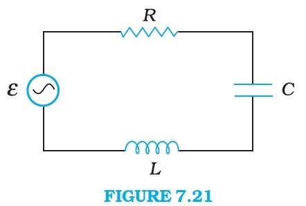
(a) Determine the source frequency which drives the circuit in resonance.
(b) Obtain the impedance of the circuit and the amplitude of current at the resonating frequency.
(c) Determine the rms potential drops across the three elements of the circuit. Show that the potential drop across the LC combination is zero at the resonating frequency.
7.11 Inductance of the Inductor, L = 5.0 H
Resistance of the resistor, R = 40 Ω
Capacitance of the capacitor, C = 80 80 F
Potential of the voltage source, V = 230 V
Resonance angular frequency is given as
= = = 50 rad/s
The impedance of the circuit is given as
Z = where = Inductive reactance and = Capacitive reactance
At resonance, = so Z = R = 40Ω
Amplitude of the current at the resonating frequency is given as
= where = Peak voltage = V
= = = 8.13 A
Hence, at resonance, the impedance of the circuit is 40 Ω and the amplitude of the current is 8.13 A.
rms potential drop across the inductor is given by
=
= = 5.75 A
= = 1437.5 V
Potential drop across capacitor,
=
= = 1437.5 V
Potential drop across resistor,
= = 5.75 = 230 V
Potential drop across LC combination
=
At resonance, = , hence
Hence, it is proved that the potential drop across the LC combination is zero at resonating frequency.
7.12 An LC circuit contains a 20 mH inductor and a 50 μF capacitor with an initial charge of 10 mC. The resistance of the circuit is negligible. Let the instant the circuit is closed be t = 0.
(a) What is the total energy stored initially? Is it conserved during LC oscillations?
(b) What is the natural frequency of the circuit?
(c) At what time is the energy stored
(i) completely electrical (i.e., stored in the capacitor)?
(ii) completely magnetic (i.e., stored in the inductor)?
(d) At what times is the total energy shared equally between the inductor and the capacitor?
(e) If a resistor is inserted in the circuit, how much energy is eventually dissipated as heat?
7.12 Inductance of the Inductor, L = 20 mH = 20 H
Capacitance of the capacitor, C = 50 = 50 F
Initial charge of the capacitor, Q = 10 mC = 10 C
The total energy stored initially at the circuit is given as
E = = = 1 J
Hence, the total energy stored in the LC circuit will be conserved because there is no resistor connected in the circuit.
Natural frequency of the circuit is given by the relation
= = 159.15 Hz
Natural angular frequency, = = 1000 rad/s
(i) Total time period, T = = = 6.28 s = 6.28 ms
Total charge on the capacitor at time t is given by
Q’ = Q t
For energy stored in electrical, we can write Q = Q’
Hence, it can be inferred that the energy stored in the capacitor is completely electrical at time, t = 0, , T , , ……
(ii) Magnetic energy is the maximum when electrical energy Q’ s equal to zero.
Hence it can be inferred that the energy stored in the capacitor is completely magnetic at time, t = ……..
Let Q’ be the charge on the capacitor when total energy is equally shared between the capacitor and the inductor a time t. When total energy is equally shared between the inductor and capacitor, the energy stored in the capacitor = (maximum energy)
= = ( ) =
= or Q’ =
We have previously obtained Q’ = Q t
Q t
t = = cos(2 , where n = 0,1,2,3…….
t = (2n+1)
Hence, total energy is equally shared between the inductor and the capacitor at time,
t = , , ,………
Resistor damps out the LC oscillations eventually. The whole of the initial energy (= 1.0 J) is eventually dissipated as heat.
7.13 A coil of inductance 0.50 H and resistance 100 Ω is connected to a 240 V, 50 Hz ac supply.
(a) What is the maximum current in the coil?
(b) What is the time lag between the voltage maximum and the current maximum?
7.13 Inductance of the Inductor, L = 0.50 H
Resistance of the resistor, R = 100 Ω
Potential of supply voltage, V = 240 V
Frequency of the supply, = 50 Hz
Peak voltage is given as = = 339.41 V
Angular frequency of the supply, = 2
Maximum current in the supply is given as
= = = 1.82 A
Equation for voltage is given as V = and equation for current is given as
I = , where phase difference between voltage and current.
At time t = 0, V = [Maximum voltage condition]
For = 0, I = [ Maximum current condition], for that t =
Hence the time lag between maximum voltage and maximum current is
Phase angle is also given by the relation,
= = = 1.5708
= rad = 1.003 rad
t = = = 3.20 s = 3.2 ms
Hence the time lag between maximum voltage and maximum current is 3.2 ms.
7.14 Obtain the answers (a) to (b) in Exercise 7.13 if the circuit is connected to a high frequency supply (240 V, 10 kHz). Hence, explain the statement that at very high frequency, an inductor in a circuit nearly amounts to an open circuit. How does an inductor behave in a dc circuit after the steady state?
7.14 Inductance of the Inductor, L = 0.50 H
Resistance of the resistor, R = 100 Ω
Potential of supply voltage, V = 240 V
Frequency of the supply, = 10 kHz = 10 Hz
Peak voltage is given as = = 339.41 V
Angular frequency of the supply, = 2
Maximum current in the supply is given as
= = = 10.80 A
Phase angle is also given by the relation,
= = = 314.16
= rad = 1.568 rad
t = = = 24.95 s = 24.95 s
It can be observed that is very small in this case. Hence, at high frequencies, the inductor amounts to an open circuit.
In a DC circuit, after a steady state is achieved, Hence, inductor L behaves like a pure conducting object.
7.15 A 100 μF capacitor in series with a 40 Ω resistance is connected to a 110 V, 60 Hz supply.
(a) What is the maximum current in the circuit?
(b) What is the time lag between the current maximum and the voltage maximum?
7.15 Capacitance of the capacitor, C = 100 = 100 F
Resistance of the resistor, R = 40 Ω
Supply voltage, V = 110 V
Frequency of the supply voltage, = 60 Hz
Angular frequency, = 2 = 2 rad/s
For a RC circuit, the impedance Z, is given by Z =
Z = = 47.996 Ω
Peak voltage, = = = 155.56 V
Peak current, = = = 3.24 A
In a capacitor circuit, the voltage lags behind the current by a phase angle of . This angle is given by the relation
= = = = 0.663
rad
= = = 1.55 s = 1.55 ms
Hence the time lag between maximum current and maximum voltage is 1.55 ms.
7.16 Obtain the answers to (a) and (b) in Exercise 7.15 if the circuit is connected to a 110 V, 12 kHz supply? Hence, explain the statement that a capacitor is a conductor at very high frequencies. Compare this behavior with that of a capacitor in a dc circuit after the steady state.
7.16 Capacitance of the capacitor, C = 100 = 100 F
Resistance of the resistor, R = 40 Ω
Supply voltage, V = 110 V
Frequency of the supply voltage, = 12 kHz = 12 Hz
Angular frequency, = 2 = 2 rad/s = 24 rad/s
For a RC circuit, the impedance Z, is given by Z =
Z = = 40 Ω
Peak voltage, = = = 155.56 V
Peak current, = = = 3.8
9 A
In a capacitor circuit, the voltage lags behind the current by a phase angle of . This angle is given by the relation
= = = = 3.315
rad
= = = 4.4 s = 0.044 s
Hence, tends to become zero at high frequencies. At a high frequency, capacitor C acts as a conductor.
In DC circuit, after the steady state is achieved, = 0
Hence, capacitor C amounts to an open circuit.
7.17 Keeping the source frequency equal to the resonating frequency of the series LCR circuit, if the three elements, L, C and R are arranged in parallel, show that the total current in the parallel LCR circuit is minimum at this frequency. Obtain the current rms value in each branch of the circuit for the elements and source specified in Exercise 7.11 for this frequency.
7.17 Inductance of the Inductor, L = 5.0 H
Resistance of the resistor, R = 40 Ω
Capacitance of the capacitor, C = 80 80 F
Potential of the voltage source, V = 230 V
Impedance Z of the given parallel LCR circuit is given as
= where = angular frequency
At resonance = 0 or =
= = 50 rad/s
The magnitude of Z is the maximum at = 50 rad/s. As a result, total current is minimum.
rms current flowing through the Inductor L is given as,
= = = 0.92 A
rms current flowing through the Capacitor C is given as,
= = 230 80 = 0.92 A
rms current flowing through resistor R is given as, = = = 5.75 A
7.18 A circuit containing a 80 mH inductor and a 60 F capacitor in series is connected to a 230 V, 50 Hz supply. The resistance of the circuit is negligible.
(a) Obtain the current amplitude and rms values.
(b) Obtain the rms values of potential drops across each element.
(c) What is the average power transferred to the inductor?
(d) What is the average power transferred to the capacitor?
(e) What is the total average power absorbed by the circuit? [‘Average’ implies ‘averaged over one cycle’.]
7.18 Inductance, L = 80 mH = 80 H
Capacitance, C = 60 = 60 F
Supply voltage, V = 230 V
Supply frequency, = 50 Hz
Peak voltage, = V = 325.27 V
Angular frequency, = 2 = 2 = 2 = 100 rad/s
Maximum current is given as:
= = = 11.65 A
The negative sign is due to
Amplitude of maximum current = 11.65 A
rms value of the current, I = = = -8.24 A
(i) Potential difference across inductor, = I = 8.24 80 V = 207.09 V
(ii) Potential drop across capacitor, = I = 8.24 = 437.14 V
Average power consumed by the inductor is zero as actual voltage leads the current by
Average power consumed by the capacitor is zero as the voltage lags current by
The total power absorbed ( average over one cycle) is zero.
7.19 Suppose the circuit in Exercise 7.18 has a resistance of 15 Ω. Obtain the average power transferred to each element of the circuit, and the total power absorbed.
7.19 Inductance, L = 80 mH = 80 H
Capacitance, C = 60 = 60 F
Resistance of the resistor, R = 15 Ω
Supply voltage, V = 230 V
Supply frequency, = 50 Hz
Peak voltage, = V = 325.27 V
Angular frequency, = 2 = 2 = 2 = 100 rad/s
Since the elements are connected in series, the impedance is given by
Z =
=
=
= 31.693 Ω
Current flowing in the circuit, I = = = 7.26 A
Average power transferred to resistance is given as = R = = 789.97 W
Average power transferred to capacitor, = 0
Average power transferred to Inductor, = 0
Total power absorbed by the circuit =
7.20 A series LCR circuit with L = 0.12 H, C = 480 nF, R = 23 Ω is connected to a 230 V variable frequency supply.
(a) What is the source frequency for which current amplitude is maximum. Obtain this maximum value.
(b) What is the source frequency for which average power absorbed by the circuit is maximum. Obtain the value of this maximum power.
(c) For which frequencies of the source is the power transferred to the circuit half the power at resonant frequency? What is the current amplitude at these frequencies?
(d) What is the Q-factor of the given circuit?
7.20 Inductance, L = 0.12 H
Capacitance, C = 480 nF = 480 F
Resistance, R = 23 Ω
Supply voltage, V = 230 V
Peak voltage is given as, = = 325.27 V
Current flowing in the circuit is given by the relation,
where = maximum at resonance
, where = Resonance angular frequency.
Hence, = = = 4166.67 rad/s
Therefore, resonating frequency = = 663.15 Hz
Maximum current = = = 14.14 A
Maximum average power absorbed by the circuit is given as
= R = = 2300 W
The power transferred to the circuit is half the power at resonant frequency
Frequencies at which power transferred is half = Δ = 2 where,
Δ = = 95.83 rad/s
= = = 15.25 Hz
Therefore = 663.15 15.25 = 647.9 Hz and 678.4 Hz
Hence, at 647.9 Hz and 678.4 Hz frequencies, the power transferred is half.
At these frequencies, current amplitude can be given as:
I’ = = = 10 A
Q factor of the given circuit can be obtained using the relation,
Q = = = 21.74
7.21 Obtain the resonant frequency and Q-factor of a series LCR circuit with L = 3.0 H, C = 27 μF, and R = 7.4 Ω. It is desired to improve the sharpness of the resonance of the circuit by reducing its ‘full width at half maximum’ by a factor of 2. Suggest a suitable way.
7.21 Given values of the LCR circuit
L = 3.0 H, C = 27 F, R = 7.4 Ω
At resonance, the angular frequency, = = = 111.11 rad/s
Q factor of the series, Q = = = 45.045
To improve the sharpness of the resonance by reducing its ‘full width at half maximum’ by a factor of 2 without changing , we need to reduce R to half i.e. R = = 3.7 Ω
7.22 Answer the following questions:
(a) In any ac circuit, is the applied instantaneous voltage equal to the algebraic sum of the instantaneous voltages across the series elements of the circuit? Is the same true for rms voltage?
(b) A capacitor is used in the primary circuit of an induction coil.
(c) An applied voltage signal consists of a superposition of a dc voltage and an ac voltage of high frequency. The circuit consists of an inductor and a capacitor in series. Show that the dc signal will appear across C and the ac signal across L.
(d) A choke coil in series with a lamp is connected to a dc line. The lamp is seen to shine brightly. Insertion of an iron core in the choke causes no change in the lamp’s brightness. Predict the corresponding observations if the connection is to an ac line.
(e) Why is choke coil needed in the use of fluorescent tubes with ac mains? Why can we not use an ordinary resistor instead of the choke coil?
7.22 (a) It is true that in any AC circuit, the applied voltage is equal to the average sum of instantaneous voltages across the series elements of the circuit. However, this is not true for rms voltages because voltage across different elements may not be in phase.
(b) A capacitor is used in the primary circuit of an induction coil. This is because when the circuit is broken, a high induced voltage is used to charge the capacitor to avoid sparks.
(c) The dc signal will appear across capacitor C because for dc signals, the impedance of an inductor (L) is negligible while the impedance of a capacitor © is very high (almost infinite). Hence, a dc signal appears across C
For an AC signal of high frequency, the impedance of L is high and that of C is very low. Hence, an AC signal of high frequency appears across L.
(d) If an iron core is inserted in the choke coil (which is in series with a lamp connected to AC line), then the lamp will glow dimly. This because the choke coil and the iron core increase the impedance of the circuit.
(e) A choke coil is needed in the use of fluorescent tubes with AC Mains because it reduces the voltage across the tube without wasting much power. An ordinary resistor cannot be used instead of choke coil for this purpose because it wastes power in the form of heat.
7.23 A power transmission line feeds input power at 2300 V to a step-down transformer with its primary windings having 4000 turns. What should be the number of turns in the secondary in order to get output power at 230 V?
7.23 Input voltage, = 2300 V
Number of turns in primary coil, = 4000
Output voltage, = 230 V
Number of turns in secondary coil =
From the relation of voltage and number of turns, we get
= or = = 400
Hence, there are 400 turns in the second winding.
7.24 At a hydroelectric power plant, the water pressure head is at a height of 300 m and the water flow available is 100 m3s–1. If the turbine generator efficiency is 60%, estimate the electric power available from the plant (g = 9.8 ms–2 ).
7.24 Height of the water pressure head, h = 300 m
Volume of water flow rate, V = 100 /s
Efficiency of turbine generator, = 60 % = 0.6
Acceleration due to gravity, g = 9.8 m/
Density of water, = kg/
Therefore, electric power available from the plant =
= 0.6
= 176.4 W
= 176.4 MW
7.25 A small town with a demand of 800 kW of electric power at 220 V is situated 15 km away from an electric plant generating power at 440 V. The resistance of the two wire line carrying power is 0.5 Ω per km. The town gets power from the line through a 4000-220 V step-down transformer at a sub-station in the town.
(a) Estimate the line power loss in the form of heat.
(b) How much power must the plant supply, assuming there is negligible power loss due to leakage?
(c) Characterize the step up transformer at the plant.
7.25 Total electric power required, P = 800 kW = 800 W
Supply voltage, V = 220 V
Electric plant generating voltage, V’ = 440 V
Distance between the town and power generating station, d = 15 km
Resistance of the two wires lines carrying power = 0.5 Ω /km
Total resistance of the wire, R = 2 = 15 Ω
Step-down transformer rating 4000 – 220 V, hence
Input voltage to the transformer, = 4000 V
Output voltage from the transformer, = 220 V
rms current in the wire lines is given as
I = = = 200 A
Line power loss = = 15 = 600 W = 600 kW
Since the leakage power loss is negligible, the total power to be supplied by plat = 800 + 600 = 1400 kW
Voltage drop in the transmission line = IR = 200 = 3000 V. Hence, the total voltage transmitted from plant = 3000 + 4000 = 7000 V
Since the power generated is 440V, the transformer rating at the plant should be 440 V – 7000 V
7.26 Do the same exercise as above with the replacement of the earlier transformer by a 40,000-220 V step-down transformer (Neglect, as before, leakage losses though this may not be a good assumption any longer because of the very high voltage transmission involved). Hence, explain why high voltage transmission is preferred?
7.26 The rating of step-down transformer = 40000 V – 220 V
Hence, the input voltage, = 40000 V
Output voltage, = 220 V
Total electric power required, P = 800 kW = 800 W
Source potential, V = 220 V
Voltage at which electric plant generates power, V’ = 440 V
Distance between the town and power generating station, d = 15 km
Resistance of the two wires lines carrying power = 0.5 Ω /km
Total resistance of the wire, R = 2 = 15 Ω
rms current in the wire lines is given as
I = = = 20 A
Line power loss = = 15 = 6 W = 6 kW
Since the leakage power loss is negligible, the total power to be supplied by plant = 800 + 6 = 806 kW
Voltage drop in the transmission line = IR = 20 = 300 V. Hence, the total voltage transmitted from plant = 300 + 40000 = 40300 V
Since the power generated is 440V, the transformer rating at the plant should be 440 V – 40300 V
Hence, power loss during transmission = = 0.744 %
In the previous exercise, power loss during transmission = = 42.86 %
Since the power loss is less for a high voltage transmission, high voltage transmission is preferred.
Complete Study Material of Class 12 Physics Chapter 7
The table below consists of important pages related to the chapter that are most useful for complete preparation.
| Relatable Study Material for Chapter 7 |
|---|
| Class 12 Physics Chapter 7 NCERT Notes |
| Alternating Current Quick Revision Notes |
| Class 12 Physics Chapter 7 NCERT Exemplar Solutions |
| Alternating Current Class 12 Formulas |
Important Topics of Class 12 Alternating Current
Covering all the topics of the chapter is really important to get good marks in the chapter. The table below consists of topics covered as per the NCERT textbook sections. Read below.
| NCERT Section | Topic covered |
|---|---|
| 7.1 | Introduction To Alternating Current |
| 7.2 | AC Voltage Applied To A Resistor |
| 7.3 | Representation Of AC Current And Voltage By Rotating Vectors — Phasors |
| 7.4 | AC Voltage Applied To An Inductor |
| 7.5 | AC Voltage Applied To A Capacitor |
| 7.6 | AC Voltage Applied To A Series LCR Circuit |
| 7.7 | Power In AC Circuit: The Power Factor |
| 7.8 | Transformers |
Other Important Topics in Alternating Current
Here are the key topics included in the chapter Alternating Current class 12.
- Peak and RMS Value of AC
- Capacitive Reactance
- Inductive Reactance
- Phasor Diagrams
- Power in AC Circuits
- Transformers
- Resonance and LC Oscillations
Class 12 Chapter 7 Alternating Current Important Formulas
The table below contains the important formulas of Chapter 7 Alternating Current:
| Concept | Formula |
|---|---|
| AC Voltage | |
| Angular Frequency | , where is frequency in Hz |
| Mean Value of AC over half cycle | , over half cycle |
| RMS Value of AC | |
| Peak Current and Voltage | , |
| AC Through Resistor (R) | |
| AC Through Inductor (L) | |
| AC Through Capacitor (C) | |
| Inductive Reactance | |
| Capacitive Reactance | |
| Impedance in R-L Circuit | |
| Impedance in R-C Circuit | |
| Impedance in R-L-C Circuit | |
| Power in AC Circuit | |
| Power Factor | |
| Resonance in LCR Circuit | |
| Resonant Frequency | |
| Quality Factor (Q) | |
| Transformer Ratio |
|
Weightage of Alternating Current in various competitive Exams
You can check the number of questions asked from this chapter in different examinations.
| Exam Name | Number of Questions | Weightage |
|---|---|---|
| JEE Main | 1-2 | 3 - 6% |
| NEET | 1-2 | 4% |
| BITSAT | 1-2 | 4% |
| CUET UG | 2-3 | 8-10% |
| CBSE | 2-3 | 12% |
Important Questions on Alternating Current in CBSE, NEET and JEE Mains
Below you can check the important questions of the chapter in various exams.
State the basic principle behind the working of an AC generator. [CBSE 2023]
The basic working principle of an AC generator is electromagnetic induction.
As per electromagnetic induction, when current is passed through a coil, a nearby placed coil experiences a change in net magnetic flux due to this an induced current gets generated in the nearby coil.
Faraday states that the net emf generated during the process is equal to the negative of the rate of change of the magnetic flux linked with the coil.
A series CR circuit with R = 200 Ω and C = (50/π) μF is connected across an ac source of peak voltage e₀ = 100 V and frequency ν = 50 Hz. Calculate (a) impedance of the circuit (Z), (b) phase angle (φ), and (c) voltage across the resistor. [Delhi 2023]
Given:
R = 200 Ω
Xc = 1/ 2πνC = π/ 2.π. 50x50. 10^-6 = 200Ω
1) Z = 200√2 Ω
phase angle (φ) : tan(ϕ)=Xc / R = 200/ 200 = 1
2) Phase angle: φ = 45∘
3) Voltage = Irms x R = 0.25 x 200 = 50 volt
An inductor of reactance 100Ω, a capacitor of reactance 50Ω, and a resistor of resistance 50Ω are connected in series with an AC source of 10 V, 50 Hz. Average power dissipated by the circuit is _______ W. [JEE Main 2025 April session]
Given: R = 50 Ω, XL = 100 Ω, and XC = 50 Ω and Vrms = 10 V.
Impedance: Z = √(R2 + (XL - XC)2).
Z = √(502 + (100 - 50)2) = √(502 + 502) ⇒ Z = 50√2 Ω
RMS current Irms = Vrms / Z.
Irms = 10 / (50√2) ⇒ 1 / (5√2) A
Average Power Dissipated (Pavg)
Pavg = Irms2R.
Pavg = (1 / (5√2))2 × 50 = (1 / (25 × 2)) × 50 = (1 / 50) × 50
Pavg = 1 W
An inductor of self inductance 1 H is connected in series with a resistor of 100 ohm and an ac supply of 100π volt, 50 Hz. Maximum current flowing in the circuit is _____ A. [JEE Main 2025 April session]
Given:
R = 100 Ω, L = 1 H, f = 50 Hz and Vmax = 100π V
Inductive reactance XL = 2πfL
XL = 2π(50).(1) = 100π Ω
Impedance of circuit Z = √(R2 + XL2).
Z = √(1002 + (100π)2) = √(1002(1 + π2))
Z = 100√(1 + π2) Ω
Maximum current:
Imax = Vmax / Z
Imax = (100π) / (100√(1 + π2))
Imax = π / √(1 + π2) A
NCERT Physics Chapter 7 Alternating Current – FAQs
Explore exams which ask questions on Physics Ncert Solutions Class 12th
Select your preferred stream
Physics Ncert Solutions Class 12th Exam
Student Forum
Other Similar chapters for you
- NCERT Physics 12th
- Electric Charges and Fields
- Electrostatic Potential and Capacitance
- Electricity
- Moving Charges and Magnetism
- Magnetism and Matter
- Electromagnetic Induction
- Alternating Current
- Electromagnetic Waves
- Ray Optics and Optical Instruments
- Wave Optics
- Dual Nature of Radiation and Matter
- Atoms
- Nuclei
- Semiconductor Electronics: Materials, Devices and
Popular Courses After 12th
Exams accepted
CA FoundationExams accepted
ICSI ExamExams accepted
BHU UET | GLAET | GD Goenka TestBachelor of Business Administration & Bachelor of Law
Exams accepted
CLAT | LSAT India | AIBEExams accepted
IPMAT | NMIMS - NPAT | SET
Exams accepted
BHU UET | KUK Entrance Exam | JMI Entrance ExamBachelor of Design in Animation (BDes)
Exams accepted
UCEED | NIFT Entrance Exam | NID Entrance ExamBA LLB (Bachelor of Arts + Bachelor of Laws)
Exams accepted
CLAT | AILET | LSAT IndiaBachelor of Journalism & Mass Communication (BJMC)
Exams accepted
LUACMAT | SRMHCAT | GD Goenka Test