 / Preparation Physics Alternating Current
A series LCR circuit is an electrical circuit that consists of an inductor (L), a capacitor (C), and a resistor (R) connected in series. This circuit is used to study the behaviour of alternating current (AC) in the presence of an inductor, resistance, and capacitance. When AC voltage is applied to an LCR series circuit. This lead to important phenomena such as resonance. A series LCR circuit is important to understand the behaviour of AC systems and is used in radio tuning, oscillators, signal processing circuits, and filters.
Important Link:
| NCERT Class 12 notes | |
| Class 12 Maths NCERT notes |
- AC Voltage Applied to a Series LCR Circuit
- Derivation: AC Voltage Applied to a Series LCR Circuit
- Application of Series LCR Circuit
- AC Voltage Applied to a Capacitor: Problems
- NCERT Physics Class 12 Chapters
- Class 12 Physics NCERT Solutions
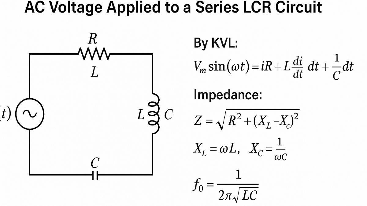
AC Voltage Applied to a Series LCR Circuit
When alternating current is applied to the series LCR circuit, the behavior of the circuit will depend on the frequency of the applied voltage. To make a series LCR circuit, we need to connect inductor, capacitor and resistor in series. In series LCR circuit, resistor allow the flow of current with no phase shift, inductor causes the current to lag, and capacitor allows the current to lead the voltage. The total impedance(Z) of the LCR circuit is expressed as:
Where,
- Inductive reactance:
- Capacitive reactance:
- Angular frequency:
The circuit may behave like a resistive, inductive, or capacitive circuit based on the frequency. At a resonant frequency (f₀), the inductive and capacitive reactances cancel out, and the circuit behaves like a pure resistor:
At resonance:
- Current is maximum
- Impedance is minimum
- Power transfer is most efficient
- Current and voltage are in phase
LCR circuits are essential in resonant power systems, tuned circuits, and radio receivers.
Also Check:
| NCERT Class 11 Notes | |
| Class 11 Chemistry NCERT notes |
Derivation: AC Voltage Applied to a Series LCR Circuit
1. Circuit Description
A LCR series circuit consists of:
- Inductor (L)
- Capacitor (C)
- Resistor (R)
LCR connected in series across the AC voltage source:
Let,
- Current through the circuit
- Inductive reactance
- Capacitive reactance:
Read More: NCERT Solutions
2. Impedance of the Circuit
The total opposition to current (impedance) is expressed as:
3. Current in the Circuit
Ohm's Law in AC circuits:
Where,
- is the phase angle between current and voltage, and is expressed as
- The circuit is inductive if
- The circuit is capacitive if
- When the circuit is resonant, and current is in phase with the voltage.
4. Resonant Frequency
At resonance:
At this frequency:
- Z=R, Impedance is minimum
- Current is maximum
- Power factor = 1
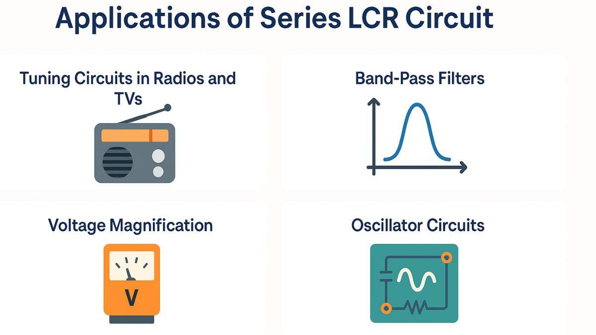
Application of Series LCR Circuit
A series LCR circuit is used in electrical and electronic systems. Here are the major applications of the LCR series circuit.
- Tuning Circuits in Radio and TVs
- A series LCR circuit is used to select specific frequencies.
- They are critical in tuned receivers, which help the devices to isolate a desired station frequency using resonance.
- Band-Pass Filters
- A series LCR circuit passes only a narrow band of frequencies at resonance, acting as a band-pass filter.
- It is used in audio processing, instrumentation, and communication systems.
- Power Supply and AC Signal Control
- It is used to suppress noise, stabilize AC voltage or allow specific frequency signals to pass through in a power circuit.
- Resonant Wireless Power Transfer
- A series LCR circuit is used in advanced technologies to tune wireless power systems for maximum efficiency by matching resonant frequencies.
- Oscillator Circuits
- These circuits are parts of LC oscillators that generate high-frequency signals for wireless transmitters, radios and function generators.
AC Voltage Applied to a Capacitor: Problems
NCERT Physics Class 12 Chapters
Students can find the link for Class 12 Physics NCERT notes below.
| Sl. No |
Name of Chapter |
|---|---|
| 1 |
Chapter 1: Electric Charges and Fields |
| 2 |
|
| 3 |
|
| 4 |
|
| 5 |
Chapter 5: Magnetism and Matter |
| 6 |
|
| 7 |
|
| 8 |
|
| 9 |
|
| 10 |
|
| 11 |
|
| 12 |
|
| 13 |
Chapter 13: Nuclei |
| 14 |
Chapter 14: Semiconductor Electronics: Materials, Devices and Simple Circuits |
Class 12 Physics NCERT Solutions
To practice for the Class 12 board exam can find the NCERT solutions for the Physics paper.
| Sl. No |
Name of Chapter |
|---|---|
| 1 |
|
| 2 |
|
| 3 |
|
| 4 |
|
| 5 |
|
| 6 |
|
| 7 |
|
| 8 |
|
| 9 |
|
| 10 |
|
| 11 |
|
| 12 |
|
| 13 |
|
| 14 |
Chapter 14 Semiconductor Electronics: Materials, Devices and Simple Circuits |
Physics Alternating Current Exam
Student Forum
Other Topics under this Chapter
- Coulomb's Law
- Power in AC Circuit
- Representation of AC Current and Voltage by Vector
- AC Voltage applied to a Series LCR circuit
- AC Voltage applied to a Capacitor
- AC Voltage Applied to an Inductor
- AC Voltage Applied to a Resistor
- Alternating Current Overview
- Combination of Resistors - Series and Parallel
- Temperature Dependence of Resistivity
- Potentiometer
- Application of Gauss's law
- Electric Dipole
- Electric Flux
- Gauss Law
Other Class 12th Physics Chapters
- Physics Alternating Current
- Physics Ray Optics and Optical Instruments
- Physics Electromagnetic Induction
- Physics Dual Nature of Radiation and Matter
- Physics Semiconductor Devices
- Physics Wave Optics
- Physics Current Electricity
- Physics Nuclei
- Physics Electrostatic Potential and Capacitance
- Physics Atoms
- Physics Moving Charges and Magnetism
- NCERT Class 12 Notes
- NCERT Class 12 Physics
- Physics Electric Charge and Field
- Physics Electromagnetic Waves
- Physics Magnetism and Matter
Popular Courses After 12th
Exams accepted
CA FoundationExams accepted
ICSI ExamExams accepted
BHU UET | GLAET | GD Goenka TestBachelor of Business Administration & Bachelor of Law
Exams accepted
CLAT | LSAT India | AIBEExams accepted
IPMAT | NMIMS - NPAT | SET
Exams accepted
BHU UET | KUK Entrance Exam | JMI Entrance ExamBachelor of Design in Animation (BDes)
Exams accepted
UCEED | NIFT Entrance Exam | NID Entrance ExamBA LLB (Bachelor of Arts + Bachelor of Laws)
Exams accepted
CLAT | AILET | LSAT IndiaBachelor of Journalism & Mass Communication (BJMC)
Exams accepted
LUACMAT | SRMHCAT | GD Goenka Test